
Page 162 - Pressure Vessel Design Manual
P. 162
140 Pressure Vessel Design Manual
PROCEDURE 3-6
SEISMIC DESIGN-VESSEL ON RINGS [4, 5, 81
C, = internal tensiodcompression coefficient
Notation Z = required section modulus, ring, in.3
IlPz = moment of inertia of rings, in. 4
C,, Ch = verticalhorizontal seismic factors S =code allowable stress, tension, psi
Ab =bearing area, in. 2 AlWz = cross-sectional area, ring, in. 2
F,, Fh = verticaVhorizonta1 seismic force, lb Tc, TT = compressiodtension loads in rings, Ib
N = number of support points M =internal moment in rings, in.-lb
n = number of gussets at supports Mb =bending moment in base ring, in.-lb, greater of
P, P, = internavexternal pressure, psi M, or My
W =vessel weight under consideration, lb B, =bearing pressure, psi
bb =bending stress, psi Q = maximum vertical load at supports, Ib
o4 = circumferential stress, psi f=radial loads on rings, lb
Kr =internal moment coefficient
Centroid qy-
f
' ring
-
! B -between
C 1
bolts
Alternate constructions
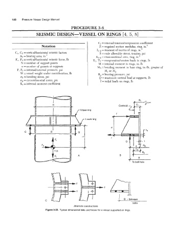
Figure 3-22. Typical dimensional data and forces for a vessel supported on rings.