
Page 157 - Pressure Vessel Design Manual
P. 157
Design of Vessel Supports 135
Calculations tension: (+) 50.66FV
compression: (-) SF, from AISC Code
1. Horizontal seismic force, FJ,.
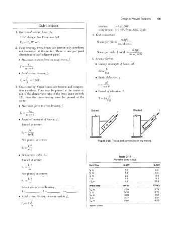
4. End connections.
lJBC design: See Procedure 3-3.
Shear per bolt = 0.5m
€71, = Ck,, W, or V
no. of bolts
2. Sway-bracing. Sway braces are tension only members,
not connected at the center. There is one per panel Shear per inch of weld = . 0.5Cf)
alternating in each adjacent panel. in. of weld
0 Maximum tension force in sway hrace,f. 5. Seismic factors.
LJ,, e Change in length of brace, Al.
f== ft
A1 1 -
0 Arid stress, tension,%. EA
f 0 Static dejlection, y,
f, = - < 0.66Fy
A A1
y=-
3. Cross-bracing. Cross braces are tension and compres- cos e
sion members. They may be pinned at the center or Period of vibration, T.
not. If the slenderness ratio of the cross brace exceeds
120, then the cross-bracing must be pinned at the
center.
0 Maximum jb-ce in cross-bracing, f.
v,, Bolted * Welded f
J1=ncOse
0 Required moment of inertia, 11.
Pinned at center
fP
I1 =-
42E
Not pinned at center Figure 3-20. Typical end connections of leg bracing.
f e2
I, =-
T2E
0 Slenderness ratio, SI.
Table 3-1 1
Pinned at center Allowable Load in kips
kl e Bolt Size A-307 A-325
SI =- ~-
2r % in. 3.1 6.4
Not pinned at center ?, in. 4.4 9.3
'/8 in. 6.0 12.6
klt 1 in. 7.9 16.5
SI =- I'/B in. 9.9 20.9
r
Weld Size EGOXX* E70XX*
Select size of cross-bracing:
I= A= r= 3/16 in. 2.39 2.78
3.18
3.71
1/4 in.
5/16 in. 3.98 4.64
0 Axial stress, tension. or compression, fa. % in. 4.77 5.57
c in. 5.56 6.50
f,= (*$
A *kipdin. of weld.