Page 152 - Pressure Vessel Design Manual
P. 152

130    Pressure Vessel Design Manual
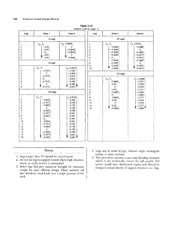
                                                          Table 3-10
                                                     Vertical Load on Legs, F,
                                           I
                  Leg1         Case 1            case2             Leg          Case 1            case 2

                                   6 Legs
                            FD-FL                               1                            FD-0.951  FL
                                                                2                                -0.588FL
                                                                3                                   0
                                                                4                                +0.588FL
                                                                5                                +0.951 FL
                                                                6                                +0.951  FL
                                                                7                                +0.588FL
                                   8 Legs                       8                                   0
                                                                9                                +0.588FL
                           FD-FL                FD-0.924FL      10                               +0.951 FL
                               -0.707F~          -0.383
                                  0                                                 12 Legs
                               +0.707FL
                               +FL                              1
                               -0.707FL          +0.383         2              - 0.866FL          -0.707
                                  0              -0.383         3              -0.5FL             -0.259
                             1 +0.707FL          -0.924         4                 0               +0.259
                                                                5              +0.5FL             t0.707
                                   16 Legs                      6              +0.866FL           +0.966
                                                                7              +FL                +0.966
                1          FD-FL                 ,-0.924        8              +0.866FL           +0.707
                2              -0.924FL          -0.382         9              +0.5FL             +0.259
                3              -0.707FL           +0.556        10                0               -0.259
                4              -0.383F~           +0.195        11             -0.5FL             -0.707
                5                 0               +0.195        12
                6              +0.383FL           +0.556
                7              +0.707F~           +OB31
                8              +0.924F~           +0.981
                9              +FL                +0.981
                10             -0.924FL           +OB31
                11             +0.707FL           +0.556
                12             -0.383F~           +0.195
                13                0               -0.195
                14             -0.383F~           -0.556
                15             -0.707FL           -0.831
                16             -0.924FL           -0.981


                                 Notes                            4. Legs may be made of pipe, channel, angle, rectangular
                                                                     tubing, or beam sections.
             1. Legs longer than 7ft should be cross-braced.      5. This procedure assumes a one-mass bending structure
             2.  Do not use legs to support vessels where high vibration,   which  is  not  technically  correct  for  tall  vessels.  Tall
               shock, or cyclic service is anticipated.              towers would  have  distributed  masses and  should be
             3.  Select legs that give  maximum strength for minimum   designed independently of support structure, i.e., legs.
               weight  for  most  efficient design. These  sections will
               also distribute local loads over a larger portion of  the
               shell.
   147   148   149   150   151   152   153   154   155   156   157