
Page 151 - Pressure Vessel Design Manual
P. 151
Design of Vessel Supports 129
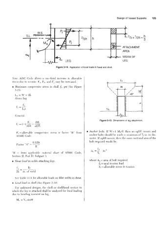
Figure 3-14. Application of local loads in head and shell.
Yote AISC Code allows a one-third increase in allowable
stress due to seismic. F,, Fi,, and Fi may be increased.
~Mazirni~rn conipressive stress in shell, fc, psi (See Figure
3-15).
Li =W+2h
Above leg:
fl
f --
- Llt
Figure 3-15. Dimensions of leg attachment.
f - (-)--- F, 4Mt
c-
TDt rD2t
Anchor bolts. If W > 4 Mdd, then no uplift occurs and
F,. = allow7ahle compressive stress is Lactor “B” from
ASME Code. anchor bolts should be made a minimum of ”/, in. in dia-
meter. If uplift occurs, then the cross-sectional area of the
bolt required would be:
fz
A,, = s; in.2
“R”= from applicable material chart of ASME Code,
Section 11, Part D, Subpart 3.
Shear load in weld.$ attaching legs. where Ab = area of bolt required
fi = axial tension load
_- 1b St = allowable stress in tension
fl
2h - in. of weld
See Table 3-11 for allowable loads on fillet welds in shear.
L0c:d load in shell (See Figure 3-14).
For unbraced designs, the shell or shellhead section to
which the leg is attached shall be analyzed for local loading
due to bending moment on leg.
M, = \’” sin 0C