
Page 156 - Pressure Vessel Design Manual
P. 156
134 Pressure Vessel Design Manual
I
CASE 1 CASE 2
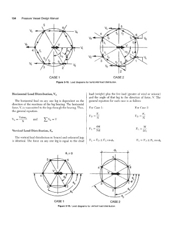
Figure 3-18. Load diagrams for horizontal load distribution.
Horizontal Load Distribution, V, load (weight) plus the live load (greater of wind or seismic)
I and the angle of that leg to the direction of force, V. The
The horizontal load on any one leg is dependent on the general equation for each case is as follows
direction of the reactions of the leg bracing. The horizontal
force, V, is transmitted to the legs through the bracing. Thus, For Case 1: For Case 2:
the general equation:
F"
FD
Vsina,
V, =- and ZV,, =V
N
FL =m
4M
Vertical Load Distribution, F,
The vertical load distribution on braced and unbraced legs
is identical. The force on any one leg is equal to the dead F, = FD f FL COS 4,
0
I
CASE 1 CASE 2
Figure 3-19. Load diagrams for vertical load distribution.