Page 159 - Pressure Vessel Design Manual
P. 159

Design of Vessel Supports   137
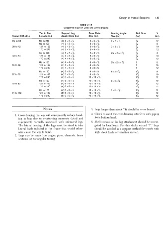
                                                         Table 3-14
                                              Suggested Sizes of Legs and Cross-Bracing
                             Tan to Tan     SUPPOfi  Leg       Base Plate      Bracing Angle     Bolt Size     Y
          Vessel O.D.  (in.)   Length (in.)   Angle Sizes (in.)   Size (in.)   Size (in.)        (in.)        (in.)

          Up to 30           Up to 240      (3) 3 x 3 x k       6x6x%          2X2X%             %             12
                             up to 120      (4) 3 x 3 x %       6x6x%                            %             8
          30 to 42           121 to 169     (4) 3 x 3 x %       6x6xX          2X2X?4            %             10
                             170 to 240     (4) 3 x 3 x %       6x6x%                            L             12
                             up to 120      (4) 3 x 3 x %       6x6x%                                          8
          43 to 54           121 to 169     (4) 3 x 3 x %       6x6x%                                          10
                             170 to 240     (4) 4 x 4 x %       8X8X%                                          12
                             up to 120      (4) 4 x 4 x %       8X8X%          2% x 2% x ‘/4     1             8
          55 to 56           121 to 169     (4) 4 x 4 x %       8X8XY2                           1             10
                             170 to 240     (4) 4 x 4 x ?h      8X8XYZ                           1             12
                             up to  120     (4) 5 x 5 x %       9X9X%          3X3X’/4           1%            8
          67 to 78           121 to 169     (4)5X5X%            9X9X%                            1%            10
                             170 to 240     (4) 6 x 6 x %       1OX1OX%                          1%            12
                             up to 120      (4) 6 x 6 x Yz      10 x 10 x Y2   3X3X3             1%            10
          79 to 80           121 to 169     (4) 6 x 6 x %       10 x 10 x Y2                     178           12
                             170 to 240     (4) 6 x 6 x %       lox lox%                         1%            12
                             up to 120      (4) 6 x 6 x %      1OX1OX%         3X3X7*            1  78         12
          91 to 102          121 to 169     (6) 6 x 6 x %      1OX1OX%                           1%            12
                             170 to 240     (6) 6 x 6 x        1ox1ox~                           1%            12


                                                                 3. Legs longer than about 7ft should be cross-braced.
                                                                 4. Check to see if the cross-bracing interferes with piping
            1. Cross-bracing the legs will conveniently reduce bend-
              ing  in  legs  due  to  overturning  moments  (wind  and   from bottom head.
              equipment)  normally  associated with  unbraced  legs.   5.  Shell stresses at the leg attachment  should be investi-
              The lateral bracing  of  the  legs must be  sized to take   gated for local loads. For thin shells, extend “Y.” Legs
              lateral loads induced in  the  frame  that would  other-   should be avoided as a support method for vessels with
              wise came the legs to bend.                           high shock loads or vibration service.
            2. Legs may be made from angles, pipes, channels, beam
              sections, or rectangular tubing.
   154   155   156   157   158   159   160   161   162   163   164