Page 164 - Pressure Vessel Design Manual
P. 164

142    Pressure Vessel Design Manual
                             / -I---.                                             f          f


                                                                    f                                      f


                                                                    f                                      f


         e             At Loads              Between Loads                         f         f

                    Kr          C,          Id          Cr     e             At Loads             Between Loads
          1"      +0.619      -0.01  7    -0.365       -1 .oo
         2"       +0.601      -0.041      -0.366      -0.999              Id         C,          K,          cr
         3"       +0.584      -0.052      -0.363      -0.998   1"       + 0.254     -1.018
         4"       +0.566      -0.071      -0.362      -0.997                                   -0.143       -1.411
          5"      +0.550      -0.087      -0.360      -0.996   2"       + 0.238     - 1.040    -0.143       -1.410
          6"      f0.532      -0.105      -0.359      -0.995   3"       + 0.221     - 1,050     -0.142      - 1.409
          7"      +0.515      -0.122      -0.357      -0.992   4"       + 0.206     - 1.066     -0.140      - 1 A08
          8"      +0.498      -0.138      -0.355      -0.990   5"       +0.194      - 1.079     -0.136      - 1.407
          9"      +0.481      -0.1  55    -0.352      -0.986   6"       +0.178      - 1,095     -0.135      - 1.406
          10"     +0.466      -0.171      -0.348      -0.985   7"       +0.165      -1.108      -0.133      - 1.405
          15"     +0.387      -0.250      -0.329      -0.966   8"       f0.153      -1.117      -0.130      - 1.404
          20"     +0.315      -0.321      -0.303      -0.940   9"       +0.141      -1.130      -0.124      - 1.397
          25"     +0.254      -0.383      -0.270      -0.906   10"      +0.130      - 1.141    -0.119       - 1.393
                                                               15"
          30"     +0.204      -0.433      -0.229      -0.866            + 0.090     -1.183     - 0.093      - 1.366
          35"     +O.  1 67   -0.469      -0.183      -0.819   20"      + 0.069     - 1.204    - 0.056      - 1.329
          40"     +o. 144     -0.492      -0.1  29    -0.766   25"      +0.069      - 1.204     - 0.008     - 1.282
          45"      +O. 137    -0.500      -0.070      -0.707   30"      + 0.090     -1.183      + 0.049     - 1.225
                                                               35"      +0.132      - 1.141    +0.115       -1.158
                                                               40"      +0.194      - 1.079     +0.190      - 1.083
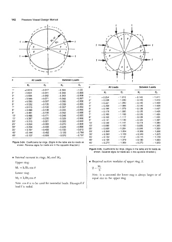
          Figure 3-24.  Coefficients for rings. (Signs in the table are for loads as   45"   + 0.273   - 1 .ooo   + 0.273   - 1 .ooo
             shown. Reverse signs for loads are in the opposite direction.)
                                                               Figure 3-25.  Coefficients for rings. (Signs in the table are for  loads as
                                                                   shown. Reverse signs for loads are in the opposite direction.)
          a Internal moment in rings, MI and M2.
            Upper ring:                                        a Required section modulus of upper ring, Z.
                                                                     M
            Mi = k,fR1 COS 8                                     Z=1
                                                                      S
            Lower ring:
                                                                 Note: It is  assumed the  lower ring is  always larger  or  of
            Mz = k,fRzcos  8                                     equal size to the upper  ring.
            Note: cos 0 is to be used for nonradial loads. Disregard if
            load f is radial.
   159   160   161   162   163   164   165   166   167   168   169