
Page 167 - Pressure Vessel Design Manual
P. 167
Design of Vessel Supports 145
PROCEDURE 3-7
SEISMIC DESIGN-VESSEL ON LUGS #1 15, 8-10]
Notation
Cl, =horizontal seismic factor
c- -vertical seismic factor
Jv
Fl, =horizontal seismic force, lb
F,. =vertical seismic force, 11)
VI, = horizontal shear per lug, lb
V,. =vertical shear per lug, lb Outer
P = internal pressure, psi
R,,, = mean radius of shell, in.
W =weight of vessel and contents, Ib C
t = shell thickness, in.
N = number of lugs
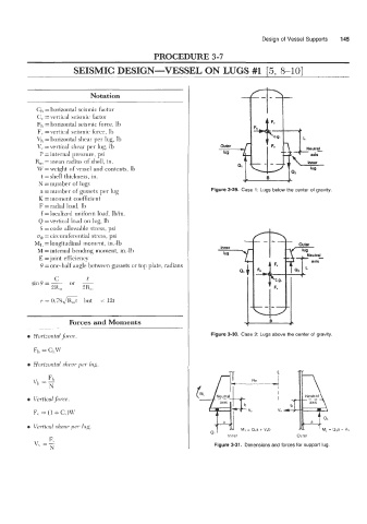
n = number of gussets per lug Figure 3-29. Case 1 : Lugs below the center of gravity.
K = moment coefficient
F = radial load, lb
f = localized uniform load, lb/in.
Q =vertical load on lug, lb
S = code allowable stress, psi
o4 = circumferential stress, psi
MI, =longitudinal moment, in.-lb
M =internal bending moment, in.-lb
E =joint efficiency
6 = one-half angle between gussets or top plate, radians
e = 0.78JK,t but < 12t
Forces and Moments
Figure 3-30. Case 2: Lugs above the center of gravity.
Fl,
VI, =
0 Vertical fiwce. 3 # Neutral
F,. = (1 + C,)W
a
0 Verticul yhenr per lug. -
VI ' Inner M, = Q,a + V,b Outer M, = Q,a - Vh
Figure 3-31. Dimensions and forces for support lug.