
Page 169 - Pressure Vessel Design Manual
P. 169
Design of Vessel Supports 147
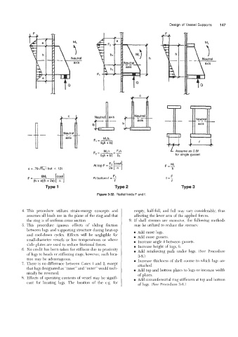
axis
I-
b axis
L Assume as 0.8P
for single gusset
M
F=-L
e = .78a but < 12t h
F
F= ~ML COS0 At bottom f = -2 f=- F
(h + e)(h + 2e) [T] 0 0
Type 2 Type 3
Figure 3-32. Radial loads F and f.
4. This procedure utilizes strain-energy concepts and empty, half-full, and f~dl may vary considerably, thus
assumes all loads are in the plane of the ring and that affecting the lever arm of the applied forces.
the ring is of uniform cross section. 9. If shell stresses are excessive, the following methods
5. This procedure ignores effects of sliding friction may be utilized to reduce the stresses:
between lugs and supporting structure during heat-up 0 Add more lugs.
and cool-down cycles. Effects will be negligible for 0 Add more gussets.
small-diameter vessels or low temperatures or where 0 Increase angle e between gussets.
slide plates are used to reduce frictional forces. 0 Increase height of lugs, 11.
6. No credit has been taken for stiffness due to proximity
of lugs to heads or stiffening rings; however, such loca- Add reinforcing pads under lugs. (See Procedure
3-8.)
tion may be advantageous.
7. There is no difference between Cases 1 and 2, except 0 Increase thickness of she11 course to which lugs are
that lugs designated as “inner” and “outer” would tech- attached .
nically be reversed. 0 Add top and bottom plates to lugs or increase width
of plates.
8. Effects of operating contents of vessel may be signifi- 0 Add circumferential ring stiffeners at top and bottom
cant for locating lugs. The location of the c.g. for
of lugs. (See Procedure 3-6.)