
Page 149 - Pressure Vessel Design Manual
P. 149
Design of Vessel Supports 127
Calculations 0 Maximum eccentric load, lb.
The following information is needed to complete the leg -Fv 4Mt
ealculations: fl=--- n nD
No. - I" = Note: fi is not considered in leg bending stress if legs are
Size - I, = not eccentrically loaded.
A= - c11=
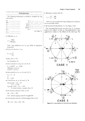
r= XI,= 0 Horizontal load distribution, V,, (See Figure 3-12).
I,= - Kl.!?/r = The horizontal load on any one given Ieg, V,, is propor-
I, = F, = tional to the stiffness of that one leg perpendicular to the
1, = (see App. L) applied force relative to the stiffness of the other legs. The
I, =
0 Deflection, y, in..
2WP
y=
3nE 12
/z \Y
Note: Limit deflection to 6 in. per lO0ft or equivalent
proportion.
0 Period of cihmtion, T, see.
\ / I \
0 Base shear, V, lb. h' I
See Procedure 3-3. w 1
0 Horizontd force at top of cessel, Fb 16. CASE 1
Ft = 0.07TV or 0.25V
whichever is less or
= 0 if T < 0.7 sec Radial
0 Horixintal.force at c.g. of cessel, Fh, 111.
F,, = V - F,
or
Fi, = Ct,u'
0 Vertical force at c.g. of uessel, F,, lb.
Downward: (-)F\. = W
or (1 + C,)W
Upward: (+)F,. = (Cv - l)\V
if vertical seismic is greater than 1.0
0 Ovwturning moment at haw, in.-lb.
Mi, = LF1, = IIF,
Note: Include piping moments if applicable.
0 Ocerturning moment at bottom tangent line, i.n.-lh.
CASE 2
M, := (L - l)Fl, + (€3 - L)Ft
Figure 3-12. Load diagrams for horizontal load distribution.