
Page 144 - Pressure Vessel Design Manual
P. 144
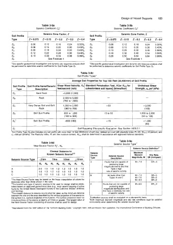
Design of  Vessel Supports   123

                              Table 3-9a                                           Table 3-9b
                          Seismic Coefficient Ca*                              Seismic Coefficient Cv*
         Soil Profile  I       Seismic Zone Factor, Z          Soil Profile         Seismic Zone Factor, 2


         Type        Z=0.075   Z=0.15   Z=0.2   Z=0.3   Z=Q.4   Type      2=0.075   Z=0.15   Z=0.2   Z=0.3   Z=0.4
                      0.06      0.12    0.16   0.24   0.32Na
                      0.08      0.15    0.20   0.30   0.40Na
                      0.09      0.18    0.24   0.33   0.40Na                         0.25    0.32    0.45   0.56Nv
                      0.12      0.22    0.28   0.36   0.44Na                0.18     0.32    0.40    0.54   0.64Nv
                      0.19      0.30    0.34   0.36   0.36Na   S€           0.26     0.50    0.64    0.84   0.96Nv
                                  See Footnote 1               SF                       See Footnote 1
         ’Sitespecific geotechnical investigation and dynamic site response analysis shall   ’Sitespecific geotechnical investigation and dynamic site response analysis shall
         be performed to determine seismic coefficients for Soil Profile Type SF.   be performed to determine seismic coefficients for Soil Profile Type SF.

                                                        Table 3-9c
                                                      Soil Profile Types‘
                                                  ~
                                                   Average Soil Properties for Top 100 Feet (30,480 mm) of Soil Profile   I
            TvDe  I      Description     feeusecond (ds)    cohesionless soil layers] (blowdfoot)   Strength, so psf (kPa)
          Soil Profile  Soil Proflle Name/Generic   Shear Wave Velocity, V,  Standard Penetration Test, N [or NcH for   Undrained Shear

                                            >5,000 (1,500)
                                                                           -                         -
                                            2,500 to 5,000
                                             (760 to 1,500)
                     Very Dense Soil and Soft   1,200 to 2,500            5 50                      > 2,000
                            Rock             (360 to 760)                                           (100)
                        Stiff Soil Profile   600 to  1,200               15 to 50                1,000 to 2,000
                                             (1 80 to 360)                                        (50 to  100)
                                                           I                                         (50)
                        Soft Soil Profile     c600 (1 80)                  ~   15           I       < 1,000     I

                                                                                                                I
                                                       Soil Requiring Site-specific Evaluation. See Section 1629.3.1.
                                                                                                                I


                                                                                   Table 3-9e
                             Table 3-9d                                        Seismic Source Type’’
                        Near-Source Factor NP, N,
                                                                                             Seismic Source Deflnitlon2
                                    Closest Distance to                                      Maximum
                                 Known Seismic Sourcezg3       Seismic      Seismic Source    Moment    Sllp Rate,
                                                               Source
                                                               TY Pe         Description    Magnitude, M  SR (mmlyear)
         Seismic Source Type   52 km   5 km   10 km   215 km
                                                               A         Faults that are capable of   M ? 7.0   SRz5
                            Nv   Na   Nv   Na   Nv   Na   Nv   Na           producing large
                                                                         magnitude events and that
         A                  2.0  1.5  1.6  1.2  1.2  1.0   1.0   1.0         have a high
         6                  1.6  1.3  1.2  1.0  1.0  1.0   1.0   1.0      rate of seismic activity
         C                  1.0  1.0  1.0  1.0  1.0  1.0   1.0   1.0   0   All faults other than   M ? 7.0   SR<5
                                                                            Types A and C     M < 7.0    SR>2
         ‘The  Near-Source Factor may be based on the linear interpolation of values for      M 26.5     SR<2
         distances other than those shown in the table.
         ’The  location and type of seismic sources to be used for design shall be estab-   C   Faults that are not capable of   M  < 6.5   SRs2
         lished based on approved geotechnical data (e.g.,  most recent mapping of active   producing large
         faults by the United States Geological Survey or the California Division of Mines   magnitude earthquakes and
         and Geology.                                                   that have a relatively low rate
         ?he  closest distance to seismic source shall be taken as the minimum distance   of seismic activity
         between the site and the area described by the vertical projection  of the source on
         the surface (i.e,, surface projection of fault plane). The surface projection need not   Subduction sources shall be evaluated on a site-specific basis.
         include portions of  the source at depths of  10 krn or greater. The largest value of   ’Both  maximum moment magnitude and  slip  rate conditions must be satisfied
         the Near-Source Factor considering all sources shall be used for design.   concurrently when determining the seismic source type.
         ‘Reproduced from the 1997 edition of the “Uniform Building Code,” copyright 1997, with permission from publisher, the International Conference of Building Officials.