
Page 141 - Pressure Vessel Design Manual
P. 141
,I] I=*& wH4 Pier or
Design of Vessel Supports
121
Step 7: The horizontal seismic force, F,,, will then be equal to Step 8: If the procedure is based on a horizontal seismic
V - Ft. This will be applied to the vessel in accordance factor, C,,, this factor shall be as follows:
with one of the appropriate procedures contained in this 1'
chapter. Ch =-
t-Support I T
YE-
8EI
T = 1.79g
I
I
See Figure 3-9.
I Note uniform weight distribution and
I
constant cross section.
2w0e 3
3NE(I, + ly)
See Figure 3-9.
Be consistent with units. H, D, and t e I, and I, are proper-
are in feet. ties of legs.
yab = deflection at B
due to lateral
load at A
See Procedure 3-9 for definitions.
Weights include
Note variation of either cross structure.
section or mass. See Note 1.
y=- W0f sin%:!
6EA
Legs over 7 ft should
be cross-braced.
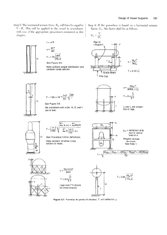
Figure 3-7. Formulas for period of vibration, T, and deflection, y.