
Page 137 - Pressure Vessel Design Manual
P. 137
Design of Vessel Supports 117
is ‘/2 mv where m =mass of air, 0.0765 PCF, and v is
the acceleration due to gravity, 32.2 ft/sec. The mass
density of the air will vary as function of altitude, lati-
tude, temperature, weather, or season. This constant
may be vaned to suit the actual conditions if they are
known with certainty. See ASCE 7-95.
4. Short, vertical vessels, vessels in structures, or horizon-
tal vessels where the height is divided between two
pressure zones may be more conveniently designed
by applying the higher pressure uniformly over the
entire vessel.
5. Vessels that qualify as “flexible” may or may not be
required to be checked for dynamic response. This
could include a dynamic analysis, which is a check of
elastic instability, or a vibration analysis for vibration
amplification due to vortex shedding. See procedure
4-8 “Vibration of Tall Towers and Stacks,” for addi-
tional information.
6. Deflection due to wind should be limited to 6in. per
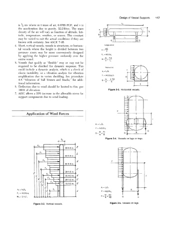
100 ft of elevation. 3-3. Horizontal vessels.
7. AISC allows a 33% increase in the allowable stress for
support components due to wind loading.
-
F
Application of Wind Forces
At = L,D,
F = AiCfGq,
W Ft‘
Q=-*-
N-8
Figure 3-4. Vessels on lugs or rings.
F
A, = We
W 4FP
o=-*-
N NB 0 Q
Figure 3-2. Vertical vessels. Figure 3-5. Vessels on legs.