
Page 138 - Pressure Vessel Design Manual
P. 138
118 Pressure Vessel Design Manual
PROCEDURE 3-2
WIND DESIGN PER UBC-97
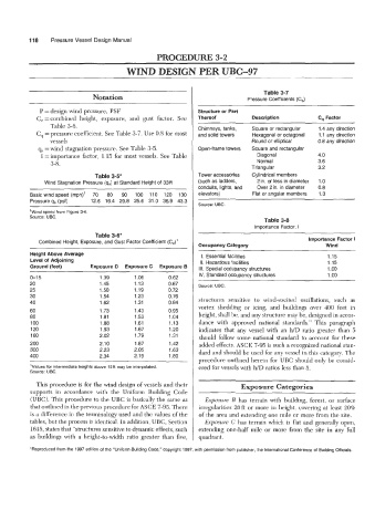
Table 3-7
Notation Pressure Coefficients (C,)
P =design wind pressure, PSF Structure or Part
C, =combined height, exposure, and gust factor. See Thereof Description C, Factor
Table 3-6. Chimneys, tanks, Square or rectangular 1.4 any direction
C, =pressure coefficient. See Table 3-7. Use 0.8 for most and solid towers Hexagonal or octagonal 1.1 any direction
vessels Round or elliptical 0.8 any direction
q, =wind stagnation pressure. See Table 3-5. Open-frame towers Square and rectangular
I =importance factor, 1.15 for most vessels. See Table Diagonal 4.0
Normal
3-8. Triangular 3.6
3.2
Table 3-5* Tower accessories Cylindrical members
Wind Stagnation Pressure (q,) at Standard Height of 33ft (such as ladders, 2 in. or less in diameter 1 .o
conduits, lights, and Over 2 in. in diameter 0.8
Basic wind speed (mph)' 70 80 90 100 110 120 130 elevators) Flat or angular members 1.3
Pressure q, (psf) 12.6 16.4 20.8 25.6 31.0 36.9 43.3
Source: UBC.
'Wind speed from Figure 3-6.
Source: UBC. Table 3-8
Importance Factor, I
Table 3-6* Importance Factor I
Combined Height, Exposure, and Gust Factor Coefficient (Ce)'
Occupancy Category Wind
Height Above Average 1. Essential facilities 1.15
Level of Adjoining II. Hazardous facilities 1.15
Ground (feet) Exposure D Exposure C Exposure B Ill. Special occupancy structures 1 .oo
~ IV. Standard occupancy structures 1 .oo
0-1 5 1.39 1.06 0.62
20 1.45 1.13 0.67 Source: UBC.
25 1.50 1.19 0.72
30 1.54 1.23 0.76 structures sensitive to wind-excited oscillations, such as
40 1.62 1.31 0.84 vortex shedding or icing, and buildings over 400 feet in
60 1.73 1.43 0.95 height, shall be, and any structure may be, designed in accor-
80 1.81 1.53 1.04
100 1.88 1.61 1.13 dance with approved national standards." This paragraph
120 1.93 1.67 1.20 indicates that any vessel with an WD ratio greater than 5
160 2.02 1.79 1.31 should follow some national standard to account for these
200 2.10 1.87 1.42 added effects. ASCE 7-95 is such a recognized national stan-
300 2.23 2.05 1.63 dard and should be used for any vessel in this category. The
400 2.34 2.19 1 .80
procedure outlined herein for UBC should only be consid-
'Values for intermediate heights above 15ft may be interpolated. ered for vessels with h/D ratios less than 5.
Source: UBC.
This procedure is for the wind design of vessels and their Exposure Categories
supports in accordance with the Uniform Building Code
(UBC). This procedure to the UBC is basically the same as Exposure B has terrain with building, forest, or surface
that outlined in the previous procedure for AXE 7-95. There irregularities 20ft or more in height, covering at least 20%
is a difference in the terminology used and the values of the of the area and extending one mile or more from the site.
tables, but the process is identical. In addition, UBC, Section Exposure C has terrain which is flat and generally open,
1615, states that "structures sensitive to dynamic effects, such extending one-half mile or more from the site in any full
as buildings with a height-to-width ratio greater than five, quadrant.
'Reproduced from the 1997 edition of the "Uniform Building Code," copyright 1997, with permission from publisher, the International Conference of Building Officials.