
Page 150 - Pressure Vessel Design Manual
P. 150
128 Pressure Vessel Design Manual
dq I
@,= 0 -1 I
1
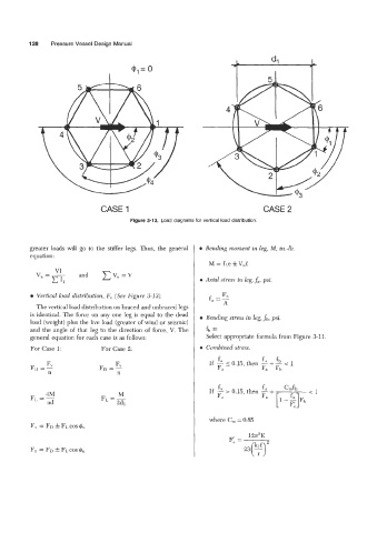
CASE 1 CASE 2
Figure 3-13. Load diagrams for vertical load distribution.
greater loads will go to the stiffer legs. Thus, the general 0 Bending moment in leg, M, in.46.
equation:
v -- VI and cV,,=V
- I, 0 Axial stress in leg, fa, psi.
0 Vertical load distribution, F,, (See Figure 3-13).
The vertical load distribution on braced and unbraced legs
is identical. The force on any one leg is equal to the dead 0 Bending stress in leg, fb, psi.
load (weight) plus the live load (greater of wind or seismic)
and the angle of that leg to the duection of force, V. The fh =
general equation for each case is as follows: Select appropriate formula from Figure 3-11.
For Case 1: For Case 2: 0 Combined stress.
fa
fa
F, If - < 0.15, then -+- fb < 1
FD =- Fa - Fa Fh
n
4M M
FL =- FL =-
nd 2dl
where C,, = 0.85
129E
F: =