Page 223 - Pressure Vessel Design Manual
P. 223

Design of  Vessel Supports   201
                                                                         0.125tSk
                                                                                -
                                                               Factor A = ___   -
                                                                            R

                                                               Factor  B = from applicable material
                                                                          chart of  ASME Code, Section 11.
                                                                          Part D, Subpart 3


                                                               Anchor Bolts

                                                               0  Force per bolt due to uplij?
                                                                     48Mb   wb
                                                                 f
                                                                  ’- dN      N

                                                               0  Required bolt urea, AI,.
                   4 :d                                        Base Plate          diameter bolts


                                                                 Use (  )
                                                                 Note: Use four ‘?$-in.-diameter bolts as a minimum.


                       Butt
                          welded
                                                                          +--
                        E = 0.7           Lap  welded            Bearing pressure, fc  (uveruge at bolt circle).
                                            E = 0.5
                                                                     48M1,  WI, -
                                                                 f,  = 2
                                                                     na     ndw
                                                               0  Required thickness of base plate, tl,.
                                                                 tt,  = I/-   3f,
                                                                        20,000

                                                               Skirt
                                                               e  Longitudinal force.s, fL,T and fL(..
                                           in.
                                       =
                                     tsK = %e  in. minimum
                                             minimum
                                     tsK
                                        %e
                   3 x  3 x  %in.
                   3
                        %in.
                       x
                      3
                    x
                   minimum
                   minimum
                                       1h-1
                                       1h-1 in.
                                           in.
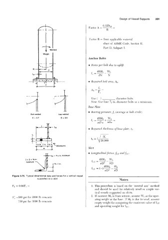
          Figure 3-76. Typical dimensional data and forces for a vertical vessel
                           supported on a skirt.                                     Notes
          FI, = 0.66FV =                                         1. This procedure  is based on the “neutral axis” method
                                                                    and should he used for relatively small or simple ver-
                                                                    tical vessels supported on skirts
                                                                 2. If moment M1,  is from seismic, assume Wi) as the oper-
          F:  =SO0 psi for 2000 lb concrete
                                                                    ating weight at the base. If MI,  is due to wind, assume
              $50 psi for 3000 lb concrete                          empty weight for computing the maxinlrim value of frAT
                                                                    and operating weight for fL(:.
   218   219   220   221   222   223   224   225   226   227   228