
Page 228 - Pressure Vessel Design Manual
P. 228
206 Pressure Vessel Design Manual
LARGE OPENING-MEMBRANE AND BENDING ANALYSIS
Notation Membrane stress, S,n nozzles without reinforcing pads
(Cases 2 and 4).
A, = area of steel, in. 2 +
(Ri(ri + t +e J-
Ap = area of pressure, in. 2 0,=P [ + Ri(T rrnt)’l
P =internal pressure, psi (design or test) AS
r, = mean radius of nozzle, in.
R, =mean radius of shell, in. a Bending stress, ab.
T =thickness of shell, in. (5 1
t = thickness of nozzle, in. M = P 2 + RiriC
Fy = minimum specified yield strength, ksi
u =maximum combined stress, psi
Ob =bending stress, psi
urn = membrane stress, psi
I = moment of inertia, in. 4
M =bending moment, in.-lb
Procedure
Step 1: Compute boundary limits for bending along shell and
nozzle in accordance with Note 3. Limit will be governed Notes
by whether material of construction has a yield strength,
F,, less than or greater than 40 ksi. 1. Openings that exceed the limits of UG-36(b)(l) shall
meet the requirements of the 2/3 rule.
Along shell = 2. This analysis combines the primary membrane stress
Along nozzle = due to pressure with the secondary bending stress
resulting from the flexure of the nozzle about the
Step 2: Utilizing the appropriate case (Figure 4-3) calculate hard axis.
the moment of inertia, I, and the distance from centroid to 3. Boundaries of metal along the shell and nozzle wall
the inside of the shell, C. are as follows:
I=
C= Along Shell Along Nozzle
Cases 1 and 2 m m
Step 3: Compute membrane and bending stresses in accor- Cases 3 and 4 1 6T 16t
dance with the equations given later.
urn =
ub = 4. This procedure applies to radial nozzles only.
Step 4: Combine stresses and compare with allowable.
urn +ub =
Calculations
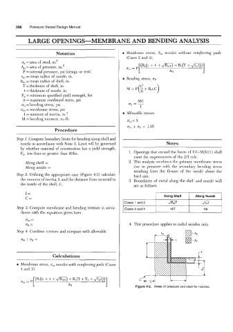
a Membrane stress, a, nozzles with reinforcing pads (Cases
1 and 3).
[ AS Figure 4-2. Areas of pressure and steel for nozzles.
urn= P (Ri(ri + t + JRZ,) + R~(T + T,! + rmt”l