
Page 232 - Pressure Vessel Design Manual
P. 232
210 Pressure Vessel Design Manual
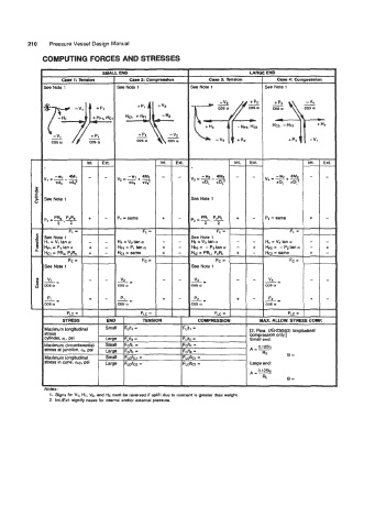
COMPUTING FORCES AND STRESSES
SMA . END LARGE END
Ca8el:lbndOn caw2 COmDreadon case 3: Tendon Case 4: Compression
See Note 1 See Note 1 See Note 1 See Note 1
Int. Ext. Int. EXt. Int. Ext.
- - - - - -
See Note 1 See Note 1
+ - PI = same + - P2 = same + -
9
=
See Note 1 - - - - -
H1 = VI tan u - -
Hpl Pi tan Q + - + - +
+ - + - + -
See Note 1
V - - v2, - - -- - -
v4
L E
ms u cos Q ms a
P
p1
P2
-= + - L= + - -= + -
ma Q COSQ
FLC = FLC = FLC =
STRESS COMPRESSION MAX. ALLOW. STRE! i COMP.
3treSs brge ~~n~ - 12, Para. “-2 bXZ) longitudinal
compression o3y.l
I
ginder, UL, psi FLkZ * Small end:
Maximum circumferential Small Fdtl- FOR1 = A 0 A
=1251
mess at junction, 0,. psi brge F,.,J~ = FJf2 = Rs
Uaximum longitudinal Small FL&,= FLdtcl= 0=
fires in cone, UW. psi
Large ~~h FLJta = large end:
~
0.12512
A=-
RL 3=
VUIIJ.
1. Signs for VI, HI, V3, and Ha must be reversed if uplift due to moment is greater than weight.
2. Intrrxt. signify cases for internal andlor external pressure.