Page 234 - Pressure Vessel Design Manual
P. 234

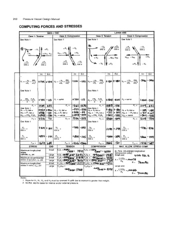
212    Pressure Vessel Design Manual

              COMPUTING FORCES AND STRESSES

                                  SMALL END                                      LARGE END
                     Case 1:  Rnsion      Case 2  Compression       Case 3 Tenslon        Case 4 Cornwemion
               be Note I               he Note 1              See Note 1              See Note 1


                                         Hci.  +:f;v2

                                             -         -
                                             COS a     COS a


                                                    Int.  I  ~xt.                                   int.   Ext.

                                                        - IRI                                      -996 -si


               see  Note 1                                    See Note 1


                                       D1 = same         - 10                         P2  = same   f-#e5  -2a

                       FL =                    FL =                   FL =                    FL =   rroq -61.
               see Note 1                                     See Note 1
               i1 = v1 tan a           H2 = Vp tan a          H3 = V3  tan a          H4 = V4 tan a   -le9  -1%
               ipl = P1 tan a          Hpl  = Pt tan a        Hm= - P2tana            Hm=  -PZtana   -717  t 10:
               icl = PRs, PxRs         Hcl  = same            He - PRL, P~RL          HCP = same   t3mr -4s
                       Fc =                   Fc =                    Fc =                    Fc =   a05 - 53'
               See  Note 1                                    See Note 1

                vi                                 -IW  -&t
                                                               v3  -
                                                                                       v4
               -=                                             --                      -=           -4% - 43c
               DS a                                           COS a                   COS a
                                                        I
               p1=                     -=          +893 -125 pP=                      -=           +##  -24
                                                                                       P2
                                        Pl
               DS a                    :os  a                 cos a                   COS a
                      FLC =                                          FLC  =                  FLC =   12% -cB;
                         ~
                     STRESS                                     COMPRESSION     I   MAX. ALLOW.  STRESS COMP.
               daximurn longitudinal
               stress
               cylinder.  UL,  psi
               Maximum circumferential
               stress at junction,  u,, psi
               Maximum longitudinal
               stress in cone, uLC, psi

               Notes:
                 1.  Signs for Vl,  HI,  VI.   and H3 must be reversed if uplift due to moment is greater than weight.
                2.  Int.lExt. signify cases for internal andlor external pressure.
   229   230   231   232   233   234   235   236   237   238   239