
Page 264 - Pressure Vessel Design Manual
P. 264
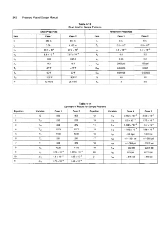
242    Pressure Vessel Design Manual

                                                         Table 4-13
                                                  Given Input for Sample Problems
          I                   Shell Properties               I                 Refractory Properties             I

          I Item           I     Case1      I     Case2       I      Item      I     Case1            Case 2
           D                      360 in.          374 in.            fL              4 in.            4 in.
                                  0.5 in.         1.125 in.          EL             0.6 x lo6         0.8 x 10⁶
           tS
           E,                   28.5 x lo6       27.7 x lo6          ffL            4.0 x            4.7 x 10⁻⁶
                                6.8 x lo-'       7.07 x 1 0-6         kL              4.4               3.2
           ffS
                                                                                                             ~
           ks                      300             331.2             PL               0.25              0.2
           PS                      0.3              0.3              gun             2000 psi         100 psi
          I Ta             I      80" F     I      -20"  F    I      STS       I     0.00028    I   ~~   0.002   --1
           TC                     60" F            50" F             STL             0.001 08        -0.00025
           TD                    1100°F            1 400"  F          hi               40               40
           P                     12 PSlG          25 PSlG             h0               4                3.5


                                                         Table 4-14
                                               Summary of Results for Sample Problems
                                                                                                                 ~
           Equation       Variable      Case 1       Case 2      Equation     Variable      Case 1      Case 2
            1                0           860          908           12          Ab        2.51 2 x 1 o-~   3.53   1 o-~
            2               Tsi          295          239           13          A14        6.8 x       1.75  10-3
            3               Ts2          296          242           14          AI5       1.832  10-3   -4.7   1 o-~
            4               TL1          1079         1377          15                    -1.02  x     1.88 x
            5                TO          1100         1400          16          UL1        -52.4psi     148.9psi
            6                TS          591          241           17          01 7      +I-1251  Dsi   +/-266~si
                                                                                                         ~
            7                TL          628          81 0          18          OL3       +I-320  psi   -1 12.5 psi
            8                u+          4320         41 55         19          OL4        -983  psi   -229.6  psi
            9                E+        1.29~10-~  1.275~10-~        20          ULS         879 psi     427.5psi
           10                All       1.6  10-3    1.28~           21          osc        -416  psi    -530  psi
           11                A 12      1.73  10-3   1.41  10-3
          I            I            I            I            I            I            I            I           I