
Page 34 - Pressure Vessel Design Manual
P. 34
20 Pressure Vessel Design Manual
possible, stiffeners should always clear shell nozzles. If una- Step 9: Select a stiffener spacing based on the maximum
voidable, special attention should be given to the design of a length of unstiffened shell (see Table 2-la). The stiffener
boxed stiffener or connection to the nozzle neck. spacing can vary up to the maximum value allowable for
the assumed thickness. Determine the number of stiffen-
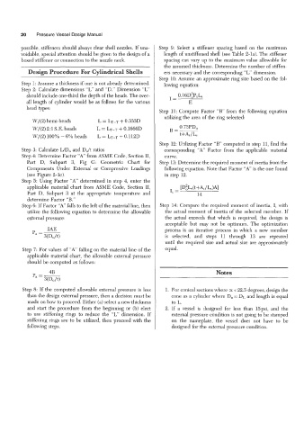
Design Procedure For Cylindrical Shells ers necessary and the correspondmg “L’ dimension.
Step 10: Assume an approximate ring size based on the fol-
Step 1: Assume a thichess if one is not already determined. lowing equation:
Step 2: Calculate dimensions “L’ and “D.” Dimension “L’
should include one-third the depth of the heads. The over- I= O.lGD~P,L,
all length of cylinder would be as follows for the various E
head types:
Step 11: Compute Factor “B” from the following equation
utilizing the area of the ring selected:
W/(2) hemi-heads L = LT-T + 0.333D
0.75PD0
W/(2) 2:1 S.E. heads L = LT-T + 0.16661) g=-
+
W/(2) 100% - 6% heads L = h-~ 0.112D t+As / Ls
Step 12: Utilizing Factor “B” computed in step 11, find the
Step 3: Calculate UD, and D,Jt ratios corresponding “A’ Factor from the applicable material
Step 4: Determine Factor “A’ from ASME Code, Section 11, curve.
Part D, Subpart 3, Fig G: Geometric Chart for Step 13: Determine the required moment of inertia from the
Components Under External or Compressive Loadings following equation. Note that Factor “A” is the one found
(see Figure 2-le). in step 12.
Step 5: Using Factor “A’ determined in step 4, enter the
applicable material chart from ASME Code, Section 11, Ls(t+As /Ls 1-41
Part D, Subpart 3 at the appropriate temperature and I, = 14
determine Factor “B.”
Step 6: If Factor “A’ falls to the left of the material line, then Step 14: Compare the required moment of inertia, I, with
utilize the following equation to determine the allowable the actual moment of inertia of the selected member. If
external pressure: the actual exceeds that which is required, the design is
acceptable but may not be optimum. The optimization
process is an iterative process in which a new member
is selected, and steps 11 through 13 are repeated
until the required size and actual size are approximately
Step 7: For values of “A’ falling on the material line of the equal.
applicable material chart, the allowable external pressure
should be computed as follows:
4B Notes
Step 8: If the computed allowable external pressure is less 1. For conical sections where c( < 22.5 degrees, design the
than the design external pressure, then a decision must be cone as a cylinder where Do = DL and length is equal
made on how to proceed. Either (a) select a new thickness to L.
and start the procedure from the beginning or (b) elect 2. If a vessel is designed for less than 15psi, and the
to use stiffening rings to reduce the “L’ hmension. If external pressure condition is not going to be stamped
stiffening rings are to be utilized, then proceed with the on the nameplate, the vessel does not have to be
following steps. designed for the external pressure condition.