
Page 38 - Pressure Vessel Design Manual
P. 38
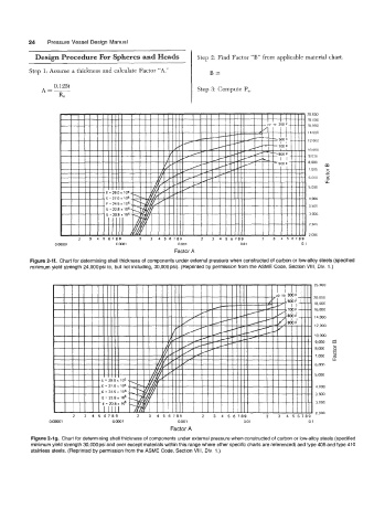
Design Procedure For Spheres and Heads              Step 2: Find Factor ‘‘€3”  from applicable material chart.

          Step 1: Assume a thickness and calculate Factor “A.”      B=

                  0.125
              A=-                                               Step 3: Compute Pa.
                    Ro


           Figure 2-If. Chart for determining shell thickness of components under external pressure when constructed of carbon or low-alloy steels (specified
           minimum yield strength 24,OOOpsi to, but not including, 30,OOOpsi).  (Reprinted by permission from the ASME Code, Section VIII, Div. 1.)


                                                                                                     25.000

                                                                                                     20.000
                                                                                                     18,OM)
                                                                                                     16.000
                                                                                                     14.000
                                                                                                     12.000
                                                                                                     lO.Oo0
                                                                                                     9.000  m
                                                                                                     8.003  5
                                                                                                           0
                                                                                                      7.000   (d
                                                                                                           u.
                                                                                                     6.000
                                                                                                     5,000
                                                                                                      4.000
                                                                                                     3,500
                                                                                                      3,000
                                                                                                      2.500
                 o.oooo1             ami                  0.001                0.01                01
                                                       Factor A
           Figure 2-1 g.  Chart for determining shell thickness of components under external pressure when constructed of carbon or low-alloy steels (specified
           minimum yield strength 30,OOOpsi and over except materials within this range where other specific charts are referenced) and type 405 and type 410
           stainless steels.  (Reprinted by permission from the ASME Code, Section VIII, Div.  1.)