
Page 40 - Pressure Vessel Design Manual
P. 40
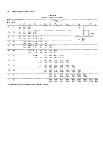
26    Pressure Vessel Design Manual

                                                         Table 2-1 b
                                                 Moment of  Inertia of Bar Stiffeners
         Thk   Max,                                            Height, h, in.
         t, in.   ht, in.
                       1    1%     2    2%     3    3%     4    4%     5     5%     6     6%      7     7%    8
          'I4   2    0.020  0.070  0.167
                     0.250  0.375  0.5
          5116   2.5   0.026  0.088  0.208  0.407
                     0.313  0.469  0.625  0.781                                        ~        r[ThS,
          "I8   3    0.031  0.105  0.25  0.488  0.844
                                                                                               th3
                     0.375  0.563  0.75  0.938  1.125                                     I=  -
          7/16   3.5       0.123  0.292  0.570  0.984  1.563                                   12
                           0.656  0.875  1.094  1.313  1.531
                4          0.141  0.333  0.651  1.125  1.786  2.667
                           0.75  1.00  1.25  1.50  1.75  2.00

          'lI6   4.5             0.375  0.732  1.266  2.00   3.00  4.271
                                 1.125  1.406  1.688  1.969  2.25  2.53
          "8    5                      0.814  1.41   2.23   3.33  4.75   6.510
                                       1.563  1.875  2.188  2.50  2.813  3.125
          11
           116   5.5                         1.55  2.46  3.67  5.22   7.16   9.53
                                             2.063  2.406  2.75  3.094  3.438  3.78
          'I4   6                            1.69  2.68  4.00  5.70   7.81   10.40  13.5
                                             2.25  2.625  3.00  3.375  3.75   4.125  4.50
          l3lI6   6.5                              2.90  4.33  6.17   8.46  11.26  14.63  18.59
                                                   2.844  3.25  3.656  4.063  4.469  4.875  5.281
                7                                        4.67  6.64   9.11  12.13  15.75  20.02  25.01
                                                         3.50  3.94   4.375  4.813  5.25   5.688  6.125
                                                                                                    _______
          1     8                                        5.33  7.59  10.42  13.86  18.00  22.89  28.58  35.16  42.67
                                                         4.00  4.50   5.00   5.50   6.00   6.50   7.00   7.50  8.00
          Note: Upper value in table is the moment of  inertia. Lower value is the area