
Page 41 - Pressure Vessel Design Manual
P. 41
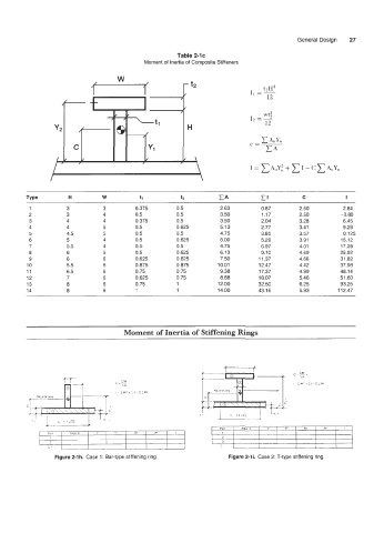
General Design   27

                                                         Table 2-lc
                                               Moment of  Inertia of  Composite Stiffeners


                                                            - f2                    ti H3
                                                                                11 =-
                                                                                     12

                     I             -                                            Iz == -
                                                            H                       12


                                                            1


                                                                                                              1
          1           3           3         0.375        0.5          2.63         0.87        2.50          2.84
          2           3          4          0.5          0.5          3.50         1.17        2.50         -3.80
          3           4          4          0.375        0.5          3.50         2.04        3.28          6.45
          4           4           5         0.5          0.625        5.13         2.77        3.41          9.28
          5           4.5        5          0.5          0.5          4.75         3.85        3.57          0.125
          6           5          4          0.5          0.625        5.00         5.29        3.91         15.12
          7           5.5        4          0.5          0.5          4.75         6.97        4.01         17.39
          8           6          5          0.5          0.625        6.13         9.10        4.69         25.92
          9           6          6          0.625        0.625        7.50        11.37        4.66         31.82
         10           5.5        6          0.875        0.875        10.01       12.47        4.42         37.98
         11           6.5        6          0.75         0.75         9.38        17.37        4.99         48.14
         12           7          6          0.625        0.75         8.88        18.07        5.46         51.60
         13           8          6          0.75         1            12.00       32.50        6.25         93.25
         14           8          6          1            1            14.00       43.16        5.93        112.47


                                        Moment of Inertia of Stiffening Rings


                  Figure 2-1 h. Case 1 : Bar-type stiffening ring.       Figure 2-li.  Case 2: T-type stiffening ring.