Page 46 - Pressure Vessel Design Manual
P. 46

32    Pressure Vessel Design Manual
                                0                                       Required Head Thickness, t,
                                -k
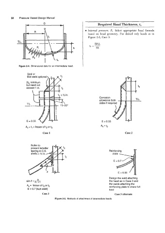
                                                              0  Znternal  pressure,  Pi. Select  appropriate  head  formula
                                                                based  on  head  geometry. For  dished  only heads  as  in
                                                                 Figure 2-5, Case 3:


              Figure 24. Dimensional data for an intermediate head.

                     Seal OF


                                                                          A,=  t,
                    A,  = t, + lesser of t2 or t,
                                Case 1                                                      Case 2


                       Butter to

                                                                                Reinforcing
                                                                                   plate
                                                t2
                                                                                   E = 0.7


                                                                                       E = 0.55

                                                                                Design the weld attaching
                            D
                    sin e =   2   ~                                             the head as in Case 3 and
                                                                                the welds attaching the
                     A,  =  lesser of t2 or t3                                  reinforcing plate to share full
                     E = 0.7 (butt weld)                                        load
                                Case 3                                              Case 3 Alternate
                                         Figure 2-5.  Methods of attachment of  intermediate heads.
   41   42   43   44   45   46   47   48   49   50   51