
Page 50 - Pressure Vessel Design Manual
P. 50
36 Pressure Vessel Design Manual
--
I I
DL *I
Figure 2-8. Dimensional data for the small end of a conical transition.
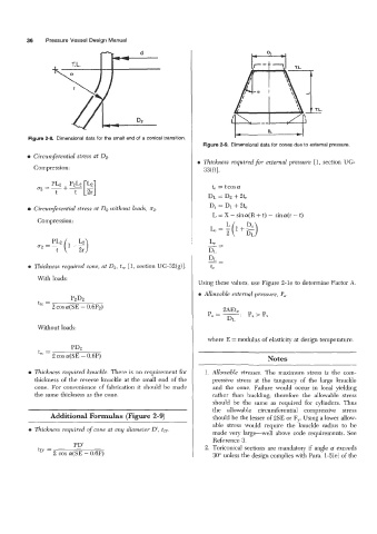
Figure 2-9. Dimensional data for cones due to external pressure.
Circumferential stress at DZ.
a Thickness required for external pressure [l, section UG-
Compression:
WOI.
te = tcosa
D~=D2+2b
D, = D1+ 2te
Circumferential stress at 02 without loads, 02.
L = X - sina(R + t) - sina(r - t)
Compression: ::)
L-- 1+-
e-:(
Thickness required cone, at DZ, t,, [l, section UG-32(g)].
With loads:
Using these values, use Figure 2-le to determine Factor A.
Allowable external pressure, Pa.
PzDz
t, =
2 cos a(SE - O.6P2)
Without loads:
where E = modulus of elasticity at design temperature.
PDz
trc =
2 COS a(SE - 0.6P) Notes
Thickness required knuckle. There is no requirement for 1. Allowable stresses. The maximum stress is the com-
thickness of the reverse knuckle at the small end of the pressive stress at the tangency of the large knuckle
cone. For convenience of fabrication it should be made and the cone. Failure would occur in local yielding
the same thickness as the cone. rather than buckling; therefore the allowable stress
should be the same as required for cylinders. Thus
the allowable circumferential compressive stress
Additional Formulas (Figure 2-9) should be the lesser of 2SE or F,. Using a lower allow-
able stress would require the knuckle radius to be
Thickness required of cone at any diameter D', tDl.
made very large-well above code requirements. See
Reference 3.
PD' 2. Toriconid sections are mandatory if angle 01 exceeds
tD' = 2 cos a(SE - 0.6P) 30" unless the design complies with Para. 1-5(e) of the