
Page 47 - Pressure Vessel Design Manual
P. 47
General Design 33
0 External pressure, P,. Assume corroded head thickness, th where P = 1.5 x greater of Pi or P,. (See Reference 1,
0.125th Figure UW-13.1.)
Factor A = ____
L 0 Shear loads on welds, F.
Factor B can be taken from applicable material charts in
Section 11, Part D, Subpart 3 of Reference 1.
Alternatively (or if Factor A lies to the left of the material/
temperature line):
B=- AE I
2 Note: sin8 applies to Figure 2-5, Case 3 head at-
pe L tachments only!
t'=B
The required head thickness shall be the greater of that 0 Shear stress, 5.
required for external pressure or that required for an in-
F
ternal pressure equal to 1.67 x P,. See Reference 1, Para. t=--
UG-33(a). AS
Shear Stress 0 Allowable shear stress, SE.
0 Hydrostatic end force, HD.
PnD2
Hn=-
4
PROCEDURE 2-6
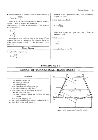
DESIGN OF TORICONICAL TRANSITIONS 11, 31
d
I I-
Notation
P = internal pressure, psi
S = allowable stress, psi
E =joint efficiency
PI, P2 = equivalent internal pressure, psi
fi, f2 = longitudinal unit loads, lb/in.
ul. uz = circumferential membrane stress, psi Anyplace on cone
a =half apex angle, deg
m=code correction factor for thickness of large
knuckle
P, =external pressure, psi
MI, M2 =longitudinal bending moment at elevation, in.-lb
WI, Wz = dead weight at elevation, lb I
D
Figure 2-6. Dimensional data for a conical transition.