
Page 45 - Pressure Vessel Design Manual
P. 45
General Design 31
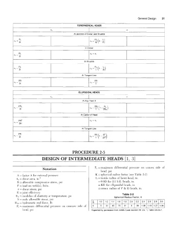
I TORISPHERICAL HEADS I
UX U
In Crown I
In Knuckle I
At Tangent Line I
I ELLIPSOIDAL HEADS I
I At Any Point X I
I At Center of Head I
I At Tangent Line I
PROCEDURE 2-5
DESIGN OF INTERMEDIATE HEADS [ 1, 31
Notation P, = maximum differential pressure on convex side of
head, psi
A = factor A for external pressure K = spherical radius factor (see Table 2-2)
A, = shear area, in.2 L =inside radius of hemi-head, in.
B = allowable compressive stress, psi =0.9D for 2:l S.E. heads, in.
F =load on weld(s), lb/in. = KD for ellipsoidal heads, in.
5 :shear stress, psi =crown radius of F & D heads, in.
E =joint efficiency
Table 2-2
El = modulus of elasticity at temperature, psi Spherical Radius Factor, K
S = code allowable stress, psi
HL) =hydrostatic end force, lb & 1.0 1.2 1.4 1.6 1.8 2.0 2.2 2.4 2.6 2.8 3.0
P, = maximum differential pressure on concave side of K .5 .57 .65 .73 .81 .9 .99 1.08 1.18 1.27 1.36
head, psi