
Page 54 - Pressure Vessel Design Manual
P. 54
40 Pressure Vessel Design Manual
TYPE 1: WELD NECK FLANGE DESIGN (INTEGRAL)
1 DESIGN CONDITIONS
Design pressure, P Allowable Stresses
Design temperature flange Bolting
flange material Design temp., SC, Design temp., sb
Bolting material Atm. temp., & Atm. temp., Sa
Corrosion allowance
-
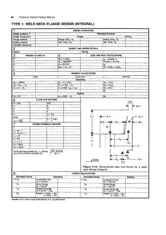
Gasket I I Facina I
3 ~ TABLES 2-3 AND 24 4 WD AND BOLT CALCULATIONS
N W, = brGy A,,, = greater of
b Hp = 2brGmP WdS. or WdSb
G H = G2rP14 Ab
Y Wm1 p Hp + H W = OW& + %)Sa
m
Ho = ~0~Pl4 hD E R + a5gl MD = Hob
HG = Wml - H hG = 0.5(c - G) MG = HGhG
HT - H - HD hT =a5(R + gl + hG) MT = HT~T
Mo
6 K AND HUB FACTORS
K=NB I I h/h, I
Z V
Y f
U e = Flh.
gllao c
d = 1 hogo2
ho =
7 STRESS FORMULA FACTORS
t
a=te+l
B = 43 te + 1
t=
I
If bolt spacing exceeds 2a + 1, multiply
m, and mG in above equation by:
Allowable Stress Operatlng Allowable Stress Seatlng
1.5 so Longitudinal hub, 1.5 S, Longitudinal hub,
SH = fm&g12 SH = fmcjhg?
s, Radial flange, Sa Radial flange,
SR = BmAt2 SR = @m&2
Sf, Tangential flan e, Sa Tangential flange,
ST = m,vn2 - 9sR ST = mGY1t2 - ZSR
SfO Greater of 0.5(SH + SR) 8. Greater of 0.5(SH + SR)
or 0.5(SH + %) or 0.5(S~ + ST)