
Page 56 - Pressure Vessel Design Manual
P. 56
42 Pressure Vessel Design Manual
Design pressure, P Allowable Stresses
Design temperature Flange Bolting
Flange material Design temp., S, Design temp., Sb
Bolting material Atm. temp., S, Atm. temp., Sa
Corrosion allowance
3 TABLES 2-3 AND 2-4 4 UMD AND BOLT CAIMILAlWNS
N Wm = b&y A,,, = greater of
b Hp = Pb&mP WmdS. or Wmdsb
G H = GZrPl4 Ab
Y W,, = Hp + H w = WA, + Ab)%
rn
Ho = &PI4 ho = O.!i(C - E) Mo = Hoho
HG= Wmt - H ho = OS(C - G) MG = HGhG
HT = H - Ho hr = aS(ho + hG) MT = HThT
Mo
FLANGE THICKNESS REQUIRED I
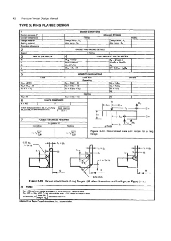
I Figure 2-12. Dimensional data and forces for a ring
t=@ flange.
Sf8
+ go
tn
I,B
La7c min
Figure 2-1 3. Various attachments of ring flanges. (All other dimensions and loadings per Figure 2-1 1 .)
8 NOTES
If g, <1.5tnand h<go I design as integral. Ifg, >1.51. andh>g,, design as ha.
ifg,sWin.. Wg. 5300, Pi300psianddesigntenp. <700', designasintegralorloose.
c=-roi t, or { loooe::am ] but not kssm 114 in.
intssrd 2g.
Adapted from Taylor Forge International. Inc., by permission.