Page 57 - Pressure Vessel Design Manual
P. 57

General Design   43

              TYPE 4:  REVERSE FLANGE DESIGN


               Design pressure, P                                         Allowabk Stresses
               &sign temperature                            Flange                            Bolting
               Flange material                 Design temp., &,               Design temp.,  Sb
               &Ring material                  Atm. temp..  E+.               Am. temp.,  S.
               conosion allowance


               3        TABLES 2-3 AND 2-4     4                     LOAD AND  BOLT CALCULATIONS
               N                               Wmz  = brGy                    An, = greater of
               b                               Hp  a Pb*GmP                   WdS. or WmtISb
               G                               H = G2rP14                     Ab
               Y                               Wmi = Hp + H                   w = WA, + &Pa
               m


               Ho = rB2PI4                     ho = OS(C + 91 - 2%-  B)       MD = HDho
               Ha = Wmi - H                    hG = 0.5(c - G)                MQ = HGhG
               &=H-HI,                         hT  o.Yc - (B + GY2)           MT = HThT
               Add moments algebraically, then use the absolute value  I Mol In all subsequent calculations.   I Mol


               K = Am'     I          I hlh,      I           I
                           I          IV          I           I


               ~        ~       ~~
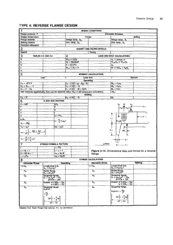
               a=te+l                  X=y+6                     Figure 2-14.  Dimensional data and forces for a reverse
               /3=4/3te+l              m. = &.le'                flange.
               y = aflR                Ilk = M;m'


               ~
               dapted from Taylor Forge International. Inc., by permission.
   52   53   54   55   56   57   58   59   60   61   62