
Page 55 - Pressure Vessel Design Manual
P. 55
General Design 41
TYPE 2: SLIP-ON FLANGE DESIGN (LOOSE)
Design preseure, P Ali~~abie Stres~~
Design temperature flange Bolting
flange material Design temp., SC, Design temp., Sb
Bolting material Atm. temp., Sh Abn. temp., S.
conosi alkwance
3 TABLES 2-3 AND 24 4 UMD AND BOU CALMllATlONS
N I W- I bffiy I A,,, = greater of
b HP = 2bffimP WdS. or Wml&
I ML I
K AND HUB FACTORS I
r-"= go =
F
le=r I
W
91 =
ho = 6 c
STRESS FOFMULA FACTORS
a=te+l B=
/3=4/3te+l t- 1 1 1
y = all I II+ C=
d = P/d
I X=r+b I I I
khT+-X
m, and m, in above equation by: hG G=
q) Bolts HG
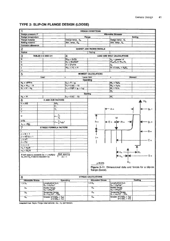
Figure 2-11. Dimensional data and forces for a slip-on
flange (loose).
- STRESS CALCULATIONS
8
Allowable Stro Operating Allowable Stresa Seating
1.5 So Longitudinal hub, 1.5 Sa Longitudinal hub,
SH = mdxg12 SH = mdxg12
SI0 Radial flange, st. Radial flange,
SR /3mdxt2 SR = Bmdxp
Tangential Ran e,
sl. Tangential Ran e. Sh ST = mYn2 -3%
E+ = m,Yn2 - ~sR
+ 4
s, Greater of 0.5(S~ + SR) Sh Greater of as(S~ + S
or o.5(SM + ST) Of
<