
Page 147 - Primer on Enhanced Oil Recovery
P. 147
Water altering gas injection 137
(A) Gas pipeline or Gas
gas producing well
Second compression
Gas
stage
Crude First compression
stage
Separators and
storage
Mixer
Water
Pumping Water/gas mixture
station
Injectic
Water well
well
(B)
Gas
Water/gas
Crude
mixture
Separators and
storage Mixer Compression
stage Water/gas mixture
Water
Injection
well
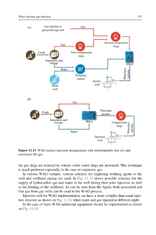
Figure 11.13 WAG surface injection arrangements with predominantly free (A) and
associated (B) gas.
the gas slugs are reduced in volume while water slugs are increased. This technique
is much preferred especially in the case of expensive gas.
In various WAG variants, various schemes for supplying working agents to the
well and wellhead piping are used. In Fig. 11.13 shows possible schemes for the
supply of hydrocarbon gas and water to the well during their joint injection, as well
as the binding of the wellhead. As can be seen from the figure, both associated and
free gas from gas wells can be used in the WAG process.
Injection well for WAG implementation can have a more complex than usual injec-
tion structure as shown on Fig. 11.14, when water and gas injected at different depth.
In the case of foam WAG additional equipment should be implemented as shown
on Fig. 11.15.