
Page 200 - Principles and Applications of NanoMEMS Physics
P. 200
188 Chapter 4
pr e pa r a tio n n
r e a do ut
“ qua ntr o niu m c ir c ui
pr e pa r a tio “ qua ntr o niu m c ir c uit” t” r e a do ut
E J J 2C
E /2 /2
2C
C C N N
g g
δ δ γ γ I (t) )
b I (t
b
U(
U(t) t)
E /2 /2
E J J φ φ E E J0 2C
2C
J0
V V I I φ φ
V(t) t)
tuning
tuning V(
(a)
U( t ) t )
U(
t t
d d
I (t ) )
I (t I I P P
b b τ τ
R R
1 1
V V th
th
V(
V( t ) t )
0 0
(b)
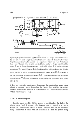
Figure 4- 3. Quantronium circuit. (a) The circuit consists of a Cooper pair box island (node
2
N), to which two small Josephson junction branches are connected. These, together with a
larger Josephson junction, that is shunted by a capacitance C (to reduce phase fluctuations),
form a loop. The state of the circuit is embodied by the number of Cooper pairs, N, and the
phases δ and γ . To tune the quantum energy levels, a DC voltage V is applied to the gate
capacitance, C , and a DC current I is forced through the coil to produce a flux φ in the
g φ
circuit loop. (b) To prepare arbitrary quantum states, microwave pulses () tU are applied to
the gate. To read out the state a current pulse () tI is applied to the large junction and the
b
resulting voltage () tV across it is measured. A typical write/read timing sequence is shown.
(After [112].)
it does not switch for a state zero. In essence, the quantronium uses a phase
circuit to measure current, instead of the charge, thus avoiding the probe-
induced decoherence problem of Nakamura et al’s. A decoherence time of
5 . 0 s µ was measured [112].
4.3.1.4.2 The Flux Qubit
The flux qubit, see Fig. 4-21(b) above, is considered as the dual of the
charge qubit [206]. It consists of a junction that is coupled to a current
source via a transformer, instead of a gate capacitor, with the junction itself
being connected in series with an inductance L , and the system being