
Page 209 - Principles and Applications of NanoMEMS Physics
P. 209
198 Chapter 5
ω ω
SP
SP
SP Light Light SP
Light
Light
C C D D A A B B
∆k
∆k AB
AB
∆k
∆k
CD
CD
k k
x x
k’ k’ x x
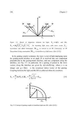
Figure 5-2. Sketch of dispersion relations for light, k = ω c , and SPs,
x
k = ω ε ε c ε + ε . An incoming light wave with wave vector k ,
'
x 1 2 1 2 x
necessitates and added momentum ∆ k to convert to an SP. Conversely, an SP
AB
Necessitates losing a momentum k∆ to transform to a light wave. (After [215].)
CD
In the grating coupler technique, the wave vector of light impinging upon
the grating-metal interface at an angle θ is resolved into one component
perpendicular to the grating-metal interface, and one component along the
interface, see Fig. 5-3. In particular, for a grating of period a, the wave
vectors along the interface are given by ω c sin ± ng , where n is an
θ
integer and g = 2π a is the reciprocal lattice vector of the grating.
Coupling between the light and the SPs is achieved when the condition,
ω ω ε
k = sin θ ± ∆ k = = k , (16)
x 0 x SP
c c ε + 1
k k
z z
k k
ω/c
ω/c
θ θ
k k
x x
∆
∆k k
x x
Fig. 5-3 Concept of grating coupler to transform light into SPs. (After [215].)