
Page 171 - Principles of Catalyst Development
P. 171
CATALYST CHARACTERIZATION 159
screens or video detectors with magnifications up to 1,000,000, at better than
0.5 nm resolution under ideal conditions. Modern detectors are amenable
to a large amount of computer image interpretation and enhancement.
Electron microscopies use sophisticated techniques, such as bright-field,
dark-field, or lattice imaging, to enhance information. A new mode of
operation, scanning transmission electron microscopy (STEM), provides
three-dimensional images for analysis at high resolli Jrt, thus extending
the range of SEM into the size region found in highly dispersed
catalysts. (203.204)
Disadvantages of this method are (1) high vacuum, (2) sample prepar-
ation, and (3) electron beam damage. Images that are recorded and analyzed
may not be representative of the average state of the catalyst. Nevertheless,
considerable information is available through TEM. One modification,
controlled atmosphere electron microscopy (CAEM), utilizes special cells
operating at pressures up to one atmosphere and to 100'C. Resolution is
reduced to 2.5 nm, but catalytic surfaces operating under dynamic conditions
have been studiedY22)
7.4.1.3. X-Ray Diffraction (XRD)
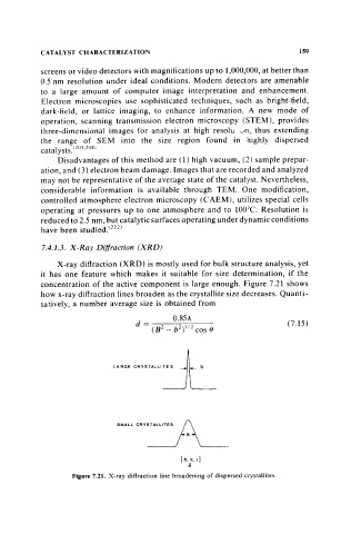
X-ray diffraction (XRD) is mostly used for bulk structure analysis, yet
it has one feature which makes it suitable for size determination, if the
concentration of the active component is large enough. Figure 7.21 shows
how x-ray diffraction lines broaden as the crystallite size decreases. Quanti-
tatively, a number average size is obtained from
(7.15)
"om ,."'''co''' A'-__ _
[h. k.1]
8
Figure 7.21. X-ray diffraction line broadening of dispersed crystallites.