
Page 232 - Principles of Catalyst Development
P. 232
CATALYST DEACTIVATION 221
10
Kp
0.1~~ __ ~ __ ~ __ ~ __ ~~
400 600 a 0-0 1000
TEMPERATURE, DC
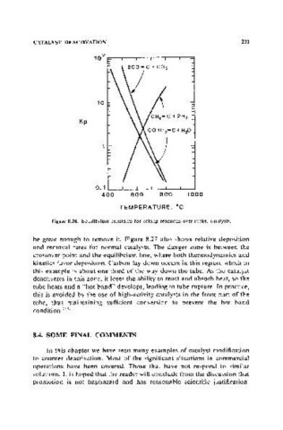
Figure 8.26. Equilibrium constants for coking reactions over nickel catalysts.
be great enough to remove it. Figure 8.27 also shows relative deposition
and removal rates for normal catalysts. The danger zone is between the
crossover point and the equilibrium line, where both thermodynamks and
kinetics favor deposition. Carbon lay-down occurs in this region, which in
this example is about one-third of the way down the tube. As the catalyst
deactivates in this zone, it loses the ability to react and absorb heat, so the
tube heats and a "hot band" develops, leading to tube rupture. In practice,
this is avoided by the use of high-activity catalysts in the front part of the
tube, thus maintaining sufficient conversion to prevent the hot band
condition. (38)
8.4. SOME FINAL COMMENTS
In this chapter we have seen many examples of catalyst modification
to counter deactivation. Most of the significant situations in commercial
operations have been covered. Those that have not respond to similar
solutions. It is hoped that the reader will conclude from the discussion that
promotion is not haphazard and has reasonable scientific justification.