
Page 287 - Process Equipment and Plant Design Principles and Practices by Subhabrata Ray Gargi Das
P. 287
11.4 Fractionator 289
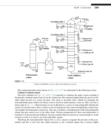
FIGURE 11.5
Crude oil distillation column with prefractionator column.
The components/subsystems shown in Figs. 11.3e11.5 are elaborated in the following section.
Column overhead system
The total condenser in Figs. 11.3 and 11.4 is expected to condense the entire vapour reaching it
through the overhead vapour line(s) from the column top. The condensed liquid drains by gravity to the
reflux drum located at a lower elevation. The drum is provided with a bleed for releasing the
noncondensable gases which will always exist in however small quantity it may be. This vent line is
shown only in Fig. 11.4. Dissolved gas (or air) in the feed is a source of noncondensable entering the
system. In vacuum towers, there is always some air leaking into the system through flange connections,
valve glands and instrument connections. This may constitute a substantial part of the noncondensable
stream that gets carried over to the reflux drum. Venting arrangement for these noncondensables is
essential to avoid any pressure build up. Vacuum columns often use ejector or vacuum pumps to create
vacuum as well as to remove the noncondensable vapour.
Throttling the noncondensable stream flow is also a means to regulate the pressure in the accu-
mulator and this in turn fixes the column pressure as the overhead vapour line is always highly