
Page 54 - Process Equipment and Plant Design Principles and Practices by Subhabrata Ray Gargi Das
P. 54
50 Chapter 3 Double pipe heat exchanger
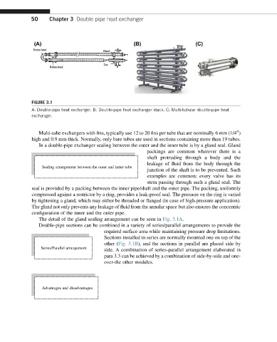
FIGURE 3.1
A: Double-pipe heat exchanger. B: Double-pipe heat exchanger stack. C: Multi-tubular double-pipe heat
exchanger.
Multi-tube exchangers with fins, typically use 12 to 20 fins per tube that are nominally 6 mm (1/4 )
00
high and 0.9 mm thick. Normally, only bare tubes are used in sections containing more than 19 tubes.
In a double-pipe exchanger sealing between the outer and the inner tube is by a gland seal. Gland
packings are common wherever there is a
shaft protruding through a body and the
leakage of fluid from the body through the
Sealing arrangement between the outer and inner tube
junction of the shaft is to be prevented. Such
examples are common; every valve has its
stem passing through such a gland seal. The
seal is provided by a packing between the inner pipe/shaft and the outer pipe. The packing, uniformly
compressed against a restrictor by a ring, provides a leak-proof seal. The pressure on the ring is varied
by tightening a gland, which may either be threaded or flanged (in case of high-pressure application).
The gland not only prevents any leakage of fluid from the annular space but also ensures the concentric
configuration of the inner and the outer pipe.
The detail of the gland sealing arrangement can be seen in Fig. 3.1A.
Double-pipe sections can be combined in a variety of series/parallel arrangements to provide the
required surface area while maintaining pressure drop limitations.
Sections installed in series are normally mounted one on top of the
other (Fig. 3.1B), and the sections in parallel are placed side by
Series/Parallel arrangement
side. A combination of series-parallel arrangement elaborated in
para 3.3 can be achieved by a combination of side-by-side and one-
over-the other modules.
Advantages and disadvantages