
Page 58 - Process Equipment and Plant Design Principles and Practices by Subhabrata Ray Gargi Das
P. 58
54 Chapter 3 Double pipe heat exchanger
3.2.5 Design considerations
Heat exchangers shall be designed to conform to specified shell side and tube side design pressure with
respect to ambient. Designs based on differential pressure of the shell and tube side is not permitted.
Minimum design pressure shall be 10% above the maximum operating pressure or maximum oper-
ating pressure plus 2 bar (200 kPa), whichever is greater. Double-pipe sections have been designed for
up to 165 bar (g) (2400 psig) pressure on the shell side and up to 1033 bar (g) (15,000 psig) pressure on
the tube side.
Minimum design temperature shall be 10% above maximum operating temperature or maximum
operating temperature plus 28 C, whichever is greater.
Tube elements shall be removable without cutting the shell or connecting piping and without
disconnecting the shell piping. One end of the tube element shall be free-floating for thermal
expansion. No internal screwed connections shall be allowed. Over-all length shall be approximately
10 m. The minimum outside tube diameter of the tube element shall be 25.4 mm (1 ) and minimum
00
thickness shall be equivalent to 12 BWG tubing or Schedule 40 pipe. All pipes and tubings used in
construction of exchangers shall be seamless.
Minimum corrosion allowance on pressurised steel pressure parts shall be 3 mm for hydrocarbon
services, except for tubes.
The heat transfer area and heat transfer coefficients shall be based on the total effective outside tube
and fin surface. The effective tube wall and fin metal resistance shall be considered in calculating the
heat transfer coefficient. Finned tubes should not be used where fouling is expected on the shell side, or
the fins are likely to be exposed to a corrosive medium. A hairpin exchanger is not permitted if fouling
is expected in the tube side.
Cooling water is normally passed through the tube side. The minimum allowed water velocity is 1 m/s.
Fouling factors for circulating cooling water may be taken 0.35 m . C/kW or 0.00,035 m . C/W
2
2
2
(0.002 ft .h. F/Btu).
The suitability of using a hairpin exchanger in a given application may be evaluated by
computing the product of heat transfer coefficient and area (UA). For preliminary evaluation, (UA)
of 80 kW/K may be considered to be the upper economic limit for hairpin type units. Above this
value, the unit may be uneconomical for a hairpin type design. If a hairpin is applied, it may require
multiple ND 400 (16 ) multi-tube sections. In the range of 53e80 kW/K one or more ND 300 (12 )
00
00
to ND 400 (16 ) multi-tube sections will normally be required. In the range of 26e53 kW/K one or
00
more ND 100 (4 )toND 300 (12 ) multi-tube sections will normally be required. Below 26 kW/K,
00
00
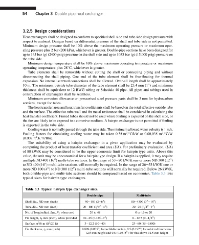
both double-pipe and multi-tube sections should be compared based on economics. Table 3.3 lists
typical sizes for hairpin type exchangers.
Table 3.3 Typical hairpin type exchanger sizes.
Double-pipe Multi-tube
Shell dia., ND mm (inch) 50e150 (2e6 ) 80e4300 (3 e16 )
00
00
00
Tube dia., ND mm (inch) 20e100 (3=4 e4 ) 20e25 (3=4 e1 )
00
00
00
00
No. of longitudinal fins, N f, when used 20 to 48 0 or 16 or 20
Fin height, h f mm (inch), when provided 10e25 (0.375e1 ) 0e12.7 (0e1=2 )
00
00
2
2
Surface m /6 m (ft /20 ft) 3e12.2 (10e40) 23e60 (75e1500)
Fin thickness, t f, mm (inch) 0.889 (0.035 ) for weldable metals, 0.5 (0.197 ) for soldered fins below
00
00
12.5 mm height and 0.8 (0.0315 ) for fins above 12.5 mm height
00