
Page 60 - Process Equipment and Plant Design Principles and Practices by Subhabrata Ray Gargi Das
P. 60
56 Chapter 3 Double pipe heat exchanger
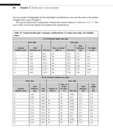
N f is the number of longitudinal fins having height h f and thickness t f on each tube and n is the number
of finned tubes, each of length L.
The typical dimensional configuration of finned tubes used in industry is shown in Table 3.4. The
exact values can also be obtained from finned tube manufacturers.
Table 3.4 Typical double-pipe exchanger configurations (A) single inner pipe, (B) multiple
pipes.
(A) 40 Schedule single inner pipe
Outer pipe Inner pipe
Wall
Nominal Wall Max. no of fins/ thickness, Fin height
diameter, inch thickness, mm OD, mm tube N f OD, mm mm h f ,mm
2 3.91 60.3 20 25.4 2.77 11.1
3 5.49 88.9 20 25.4 2.77 23.8
3.5 5.49 88.9 36 48.3 3.68 12.7
3.5 5.74 101.6 40 60.3 3.91 12.7
4 6.02 114.3 36 48.3 3.68 25.4
4 6.02 114.3 40 60.3 3.91 19.05
4 6.02 114.3 48 73.0 5.16 12.7
(B) 40 Schedule multiple inner pipes
Outer pipe Inner pipe
Max. no Fin
Wall of fins Wall height
Nominal thickness, OD, Number of per tube, thickness, h f ,
diameter, inch mm mm tubes, n N f OD, mm mm mm
4 6.02 114.3 7 16 19.02 2.11 5.33
4 6.02 114.3 7 20 22.2 2.11 5.33
6 7.11 168.3 19 16 19.02 2.11 5.33
6 7.11 168.3 14 16 19.02 2.11 5.33
6 7.11 168.3 7 20 20.04 2.77 12.7
8 8.18 219.1 19 16 19.02 2.11 8.64
8 8.18 219.1 19 20 22.2 2.11 7.11
8 8.18 219.1 19 20 25.4 2.77 5.33
8 8.18 219.1 19 16 19.02 2.11 7.11
8 8.18 219.1 19 20 22.2 2.11 5.33