
Page 342 - Programming Microcontrollers in C
P. 342
Digital Signal Processor Operations 327
lator M register. This register is 36 bits long. For convenience, the
register is broken into two portions, bits 35 through 16 and bits 15
through 0. We will see later that different portions of this register are
moved by different instructions, so that breaking this register into
the two parts is logical.
The last register in the DSP register model is the MAC XY mask
register. Automatic selection of the addresses for the next multiply
needs modulo arithmetic. We will see more modulo arithmetic later.
The mask register contains the modulo base for both the x and y
index registers which will allow fixed coefficient tables, that can be
manipulated as either single-or two-dimensional arrays, to be tra
versed automatically during successive multiply and accumulate
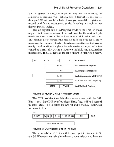
instructions. The DSP register model is shown in Figure 6-2 below.
20 16 15 8 7 0 Bit Position
HR MAC Multiplier Register
I R MAC Multplican Register
AM MAC Accumulator MSB[35-16]
A M MAC Accumulator LSB[15-0]
XMSK YMSK MAC XY Mask Register
Figure 6-2: MC68HC16 DSP Register Model
The CCR contains three bits that are associated with the DSP.
Bits 14 and 12 are DSP overflow flags. These flags will be discussed
in detail later. Bit 4 is called the SM bit and is the DSP saturation
mode control bit.
15 3 0
S MV H EV N Z V C l1 l2 l3 SM PK CCR
DSP Control Bits
Figure 6-3: DSP Control Bits In The CCR
The accumulator is 36 bits with the radix point between bits 31
and 30. When accumulating into the MAC accumulator AM, there are