
Page 106 - Programming the Photon Getting Started With the Internet of Things
P. 106
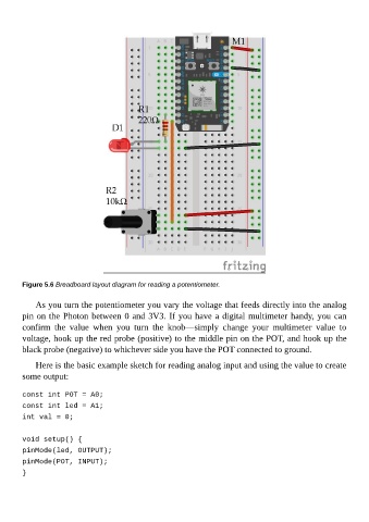
Figure 5.6 Breadboard layout diagram for reading a potentiometer.


             As you turn the potentiometer you vary the voltage that feeds directly into the analog
        pin on the Photon between 0 and 3V3. If you have a digital multimeter handy, you can
        confirm  the  value  when  you  turn  the  knob—simply  change  your  multimeter  value  to

        voltage, hook up the red probe (positive) to the middle pin on the POT, and hook up the
        black probe (negative) to whichever side you have the POT connected to ground.

             Here is the basic example sketch for reading analog input and using the value to create
        some output:


        const int POT = A0;
        const int led = A1;

        int val = 0;


        void setup() {
        pinMode(led, OUTPUT);
        pinMode(POT, INPUT);

        }