
Page 110 - Programming the Photon Getting Started With the Internet of Things
P. 110
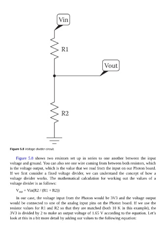
Figure 5.8 Voltage divider circuit.


             Figure  5.8  shows  two  resistors  set  up  in  series  to  one  another  between  the  input
        voltage and ground. You can also see one wire coming from between both resistors, which

        is the voltage output, which is the value that we read from the input on our Photon board.
        If  we  first  consider  a  fixed  voltage  divider,  we  can  understand  the  concept  of  how  a
        voltage  divider  works.  The  mathematical  calculation  for  working  out  the  values  of  a
        voltage divider is as follows:

             V  = Vin(R2 / (R1 + R2))
               out

             In our case, the voltage input from the Photon would be 3V3 and the voltage output
        would be connected to one of the analog input pins on the Photon board. If we use the
        resistor values for R1 and R2 so that they are matched (both 10 K in this example), the

        3V3 is divided by 2 to make an output voltage of 1.65 V according to the equation. Let’s
        look at this in a bit more detail by adding our values to the following equation: