Page 112 - Programming the Photon Getting Started With the Internet of Things
P. 112

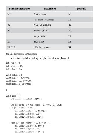
Schematic Reference                       Description                           Appendix


          M1                             Photon board                              M1


                                         400-point breadboard                      H1


          R4                             Photocell (200 K)                         R4


          R5                             Resistor (10 K)                           R3


                                         Jumper wires                              H2


          D1                             RGB LED                                   S3


          R1, 2, 3                       220-ohm resistor                          R1


        Table 5.2 Components and Equipment

             Here is the sketch for reading the light levels from a photocell:


        int red = D0;
        int green = D2;
        int blue = D1;


        void setup() {
        pinMode(red, OUTPUT);
        pinMode(green, OUTPUT);

        pinMode(blue, OUTPUT);


        }


        void loop() {
            int value = analogRead(A0);


            int percentage = map(value, 0, 4095, 0, 100);

            if (percentage < 33) {
                digitalWrite(green, HIGH);
                digitalWrite(red, LOW);
                digitalWrite(blue, LOW);

            }
            else if (percentage > 33 & < 66) {
                digitalWrite(green, LOW);
                digitalWrite(red, LOW);

                digitalWrite(blue, HIGH);
   107   108   109   110   111   112   113   114   115   116   117