
Page 148 - Programming the Photon Getting Started With the Internet of Things
P. 148
The relay shield uses a switch mode regulator that provides a constant 5 V to the
Particle and the relays. The regulator is rated at 1.2 A maximum output current, which is
sufficient to power the Photon and the four relays while still having power left over to
control other things that you connect to the Photon device. You can power the relay shield
using the DC socket or through a screw terminal with a voltage range between 7 and 20 V
DC.
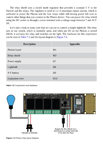
Let’s take a look at some code that we can use to control a simple lightbulb. The relay
acts as our switch, which is normally open, and when pin D3 on the Photon is turned
HIGH, it activates the relay and switches on the light. The hardware for this experiment
can be seen in Table 7.2 and the layout diagram in Figure 7.4.
Description Appendix
Photon board M1
Relay shield M3
Power supply H7
Lightbulb H8
9-V battery H9
Equipment wire H10
Table 7.2 Components and Hardware
Figure 7.4 Photon relay layout diagram.