
Page 144 - Programming the Photon Getting Started With the Internet of Things
P. 144
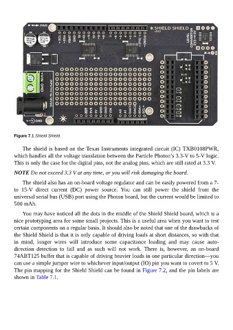
Figure 7.1 Shield Shield.


             The shield is based on the Texas Instruments integrated circuit (IC) TXB0108PWR,
        which handles all the voltage translation between the Particle Photon’s 3.3-V to 5-V logic.
        This is only the case for the digital pins, not the analog pins, which are still rated at 3.3 V.

        NOTE Do not exceed 3.3 V at any time, or you will risk damaging the board.


             The shield also has an on-board voltage regulator and can be easily powered from a 7-
        to  15-V  direct  current  (DC)  power  source.  You  can  still  power  the  shield  from  the
        universal serial bus (USB) port using the Photon board, but the current would be limited to
        500 mAh.


             You may have noticed all the dots in the middle of the Shield Shield board, which is a
        nice prototyping area for some small projects. This is a useful area when you want to test
        certain components on a regular basis. It should also be noted that one of the drawbacks of
        the Shield Shield is that it is only capable of driving loads at short distances, so with that
        in  mind,  longer  wires  will  introduce  some  capacitance  loading  and  may  cause  auto-

        direction  detection  to  fail  and  as  such  will  not  work.  There  is,  however,  an  on-board
        74ABT125 buffer that is capable of driving heavier loads in one particular direction—you
        can use a simple jumper wire to whichever input/output (IO) pin you want to covert to 5 V.

        The pin mapping for the Shield Shield can be found in Figure 7.2, and the pin labels are
        shown in Table 7.1.