
Page 32 - Programming the Photon Getting Started With the Internet of Things
P. 32
read values from analog sensors.
Tx and Rx These pins are used for communication over serial/Universal
Asynchronous Receiver Transmitter (UART). Tx represents the transmitting pin, and
Rx represents the receiving pin in the serial communication.
WKP Active-high wakeup pin; wakes the module from sleep/standby modes. When
not in use, the WAKEUP pin can be used as a GPIO, analog-to-digital convertor
(ADC), or pulse width modulation (PWM) pin.
DAC Twelve-bit digital-to-analog output and also a digital GPIO. DAC is used as
DAC or DAC1 in software, and pin A3 is used as a second DAC output as DAC2.
In addition to the GPIO pins, some of the analog and digital pins can be used as PWM
pins using the function analogWrite(). These PWM pins do something called pulse width
modulation, and they give the effect of increasing or decreasing the timings of switching
something on or off—for example, you can dim the brightness of an LED or speed up a
motor. The Photon has up to nine PWM pins: D0 to D3, A4, A5, WKP, Rx, and Tx.
Getting Connected
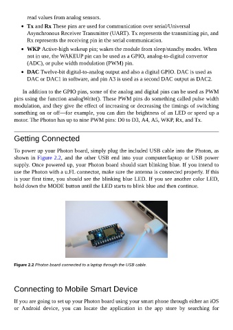
To power up your Photon board, simply plug the included USB cable into the Photon, as
shown in Figure 2.2, and the other USB end into your computer/laptop or USB power
supply. Once powered up, your Photon board should start blinking blue. If you intend to
use the Photon with a u.FL connector, make sure the antenna is connected properly. If this
is your first time, you should see the blinking blue LED. If you see another color LED,
hold down the MODE button until the LED starts to blink blue and then continue.
Figure 2.2 Photon board connected to a laptop through the USB cable.
Connecting to Mobile Smart Device
If you are going to set up your Photon board using your smart phone through either an iOS
or Android device, you can locate the application in the app store by searching for