
Page 162 - Radar Technology Encyclopedia
P. 162
152 duplexer, balanced DUTY FACTOR [CYCLE, RATIO]
higher power-handling capability than the first one, but its mitter power from entering the receiver; in the second case
bandwidth is less. SAL the open circuit of the ATR, being a quarter-wave from the
Ref.: Skolnik (1980), p. 360. transmission line, appears as a short circuit across the line.
This disconnects the transmitter from the line because the
short circuit is a quarter wave from the receiver branch-line,
and so the echo signal is directed to the receiver.
This type of duplexer is one of the earliest duplexers used
in radar. It has limited power-handling capability and band-
width, and in modern radars has generally been replaced by
balanced duplexers and other protection devices. SAL
Ref.: Skolnik (1980), p. 360.
A diode duplexer uses diode switches in place of TR tubes.
Typically, PN and PIN diodes operating unbiased or with a dc
forward bias current are used. Unbiased (passive) operation is
used for low-power application, while biased operation
(active) is capable of switching high power. If the single
Figure D57 Balanced duplexer using dual TR tubes and two diode cannot withstand the required voltage, multiple diodes
short-slot hybrid junctions: (a) transmit condition (b) receive can be used. The typical example is a balanced duplexer that
condition (from Skolnik, 1980, Fig. 9.6, p. 361, reprinted by
uses 32 PIN diodes instead of TR tubes and handles 150 kW
permission of McGraw-Hill).
peak power and 10 kW average power, with a pulse width of
200 ms. SAL
Ref.: Fink (1975), p. 25.71; Skolnik (1980), p. 363.
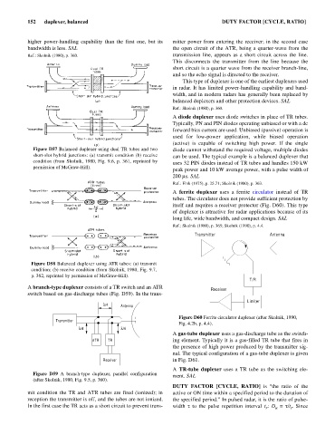
A ferrite duplexer uses a ferrite circulator instead of TR
tubes. The circulator does not provide sufficient protection by
itself and requires a receiver protector (Fig. D60). This type
of duplexer is attractive for radar applications because of its
long life, wide bandwidth, and compact design. SAL
Ref.: Skolnik (1980), p. 365; Skolnik (1990), p. 4.4.
Transmitter Antenna
Figure D58 Balanced duplexer using ATR tubes: (a) transmit
condition; (b) receive condition (from Skolnik, 1980, Fig. 9.7,
p. 362, reprinted by permission of McGraw-Hill).
T/R
A branch-type duplexer consists of a TR switch and an ATR
Receiver
switch based on gas-discharge tubes (Fig. D59). In the trans-
Limiter
l/4 Antenna
Figure D60 Ferrite circulator duplexer (after Skolnik, 1990,
Transmitter
Fig. 4.2b, p. 4.4).
l/4 l/4
A gas-tube duplexer uses a gas-discharge tube as the switch-
ATR TR ing element. Typically it is a gas-filled TR tube that fires in
the presence of high power produced by the transmitter sig-
nal. The typical configuration of a gas-tube duplexer is given
Receiver in Fig. D61.
A TR-tube duplexer uses a TR tube as the switching ele-
Figure D59 A branch-type duplexer, parallel configuration
ment. SAL
(after Skolnik, 1980, Fig. 9.5, p. 360).
DUTY FACTOR [CYCLE, RATIO] is “the ratio of the
mit condition the TR and ATR tubes are fired (ionized); in active or ON time within a specified period to the duration of
reception the transmitter is off, and the tubes are not ionized. the specified period.” In pulsed radar, it is the ratio of pulse-
In the first case the TR acts as a short circuit to prevent trans- width t to the pulse repetition interval t : D = t/t . Since
r
u
r