
Page 167 - Radar Technology Encyclopedia
P. 167
157 ECM, active ECM, cross-polarization
Active ECM incorporates devices and methods based on
deliberate radiation of electromagnetic energy to disrupt the
operation of the victim radar. Active ECM typically means
active jamming. SAL
Ref.: Barton (1991), p. 12-5; Chrzanowski (1990), p. 8.
Angle-measurement ECM is designed to cause disruption of
correct determining of the target’s angular direction both by
search and tracking radars. The main methods to counter a
search radar are to jam it through antenna sidelobes, based on
the fact that, if a signal is received and detected, it is consid-
ered to be in the antenna main beam. So, if the energy of the
signal radiated by a jammer and received by radar through
antenna sidelobes is sufficient to exceed the detection thresh-
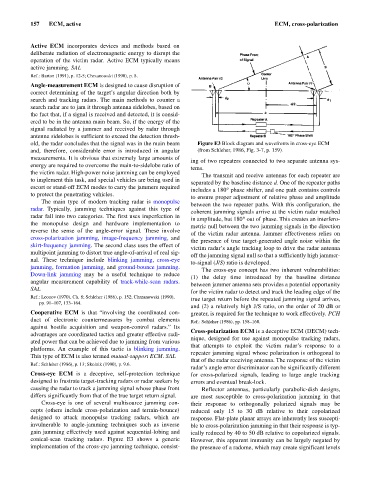
old, the radar concludes that the signal was in the main beam Figure E3 Block diagram and wavefronts in cross-eye ECM
and, therefore, considerable error is introduced in angular (from Schleher, 1986, Fig. 3-7, p. 159).
measurements. It is obvious that extremely large amounts of
ing of two repeaters connected to two separate antenna sys-
energy are required to overcome the main-to-sidelobe ratio of
tems.
the victim radar. High-power noise jamming can be employed
The transmit and receive antennas for each repeater are
to implement this task, and special vehicles are being used in
separated by the baseline distance d. One of the repeater paths
escort or stand-off ECM modes to carry the jammers required
includes a 180°phase shifter, and one path contains controls
to protect the penetrating vehicles.
to ensure proper adjustment of relative phase and amplitude
The main type of modern tracking radar is monopulse
between the two repeater paths. With this configuration, the
radar. Typically, jamming techniques against this type of
coherent jamming signals arrive at the victim radar matched
radar fall into two categories. The first uses imperfection in
in amplitude, but 180° out of phase. This creates an interfero-
the monopulse design and hardware implementation to
metric null between the two jamming signals in the direction
reverse the sense of the angle-error signal. These involve
of the victim radar antenna. Jammer effectiveness relies on
cross-polarization jamming, image-frequency jamming, and
the presence of true target-generated angle noise within the
skirt-frequency jamming. The second class uses the effect of
victim radar’s angle tracking loop to drive the radar antenna
multipoint jamming to distort true angle-of-arrival of real sig-
off the jamming signal null so that a sufficiently high jammer-
nal. These technique include blinking jamming, cross-eye
to-signal (J/S) ratio is developed.
jamming, formation jamming, and ground-bounce jamming.
The cross-eye concept has two inherent vulnerabilities:
Down-link jamming may be a useful technique to reduce
(1) the delay time introduced by the baseline distance
angular measurement capability of track-while-scan radars.
between jammer antenna sets provides a potential opportunity
SAL
for the victim radar to detect and track the leading edge of the
Ref.: Leonov (1970), Ch. 8; Schleher (1986), p. 152; Chrzanowski (1990),
true target return before the repeated jamming signal arrives,
pp. 91–107, 133–164.
and (2) a relatively high J/S ratio, on the order of 20 dB or
Cooperative ECM is that “involving the coordinated con- greater, is required for the technique to work effectively. PCH
duct of electronic countermeasures by combat elements Ref.: Schleher (1986), pp. 158–160.
against hostile acquisition and weapon-control radars.” Its
Cross-polarization ECM is a deceptive ECM (DECM) tech-
advantages are coordinated tactics and greater effective radi-
nique, designed for use against monopulse tracking radars,
ated power that can be achieved due to jamming from various
that attempts to exploit the victim radar’s response to a
platforms. An example of this tactic is blinking jamming.
repeater jamming signal whose polarization is orthogonal to
This type of ECM is also termed mutual-support ECM. SAL
that of the radar receiving antenna. The response of the victim
Ref.: Schleher (1986), p. 13; Skolnik (1990), p. 9.6.
radar’s angle error discriminator can be significantly different
Cross-eye ECM is a deceptive, self-protection technique for cross-polarized signals, leading to large angle tracking
designed to frustrate target-tracking radars or radar seekers by errors and eventual break-lock.
causing the radar to track a jamming signal whose phase front Reflector antennas, particularly parabolic-dish designs,
differs significantly from that of the true target return signal. are most susceptible to cross-polarization jamming in that
Cross-eye is one of several multisource jamming con- their response to orthogonally polarized signals may be
cepts (others include cross-polarization and terrain-bounce) reduced only 15 to 30 dB relative to their copolarized
designed to attack monopulse tracking radars, which are response. Flat-plate planar arrays are inherently less suscepti-
invulnerable to angle-jamming techniques such as inverse ble to cross-polarization jamming in that their response is typ-
gain jamming effectively used against sequential-lobing and ically reduced by 40 to 50 dB relative to copolarized signals.
conical-scan tracking radars. Figure E3 shows a generic However, this apparent immunity can be largely negated by
implementation of the cross-eye jamming technique, consist- the presence of a radome, which may create significant levels